Installation
2-2
M370185-01
Basic Setup Procedure
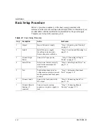
Table 2-1 provides a summary of the basic setup procedure with
references to the relevant sections in this chapter. Refer to this table if you
are unfamiliar with the installation requirements for the power supply.
Complete each step in the sequence given.
Table 2-1
Basic Setup Procedure
Step
Description
Action
Reference
1
Inspect
Inspect the power supply.
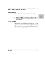
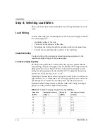
“Step 1: Inspecting and Cleaning”
on page 2–3.
2
Install
Install the power supply
(benchtop or rack mount).
Ensure adequate ventilation.
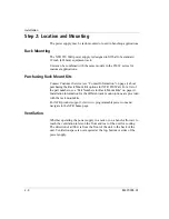
“Step 2: Location and Mounting” on
page 2–4.
3
Connect Input
Power
Connect AC input power.
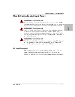
“Step 3: Connecting AC Input
Power” on page 2–5.
4
Select Wires
Select wires that are correctly
rated for the maximum DC
output current.
“Step 4: Selecting Load Wires” on
page 2–6.
5
Test
Perform functional tests for
voltage mode operation, current
mode operation, and front panel
controls.
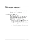
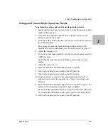
“Step 5: Performing Functional
Tests” on page 2–8.
6
Connect Loads
Connect the load wires to the
DC output.
“Step 6: Connecting Loads” on
page 2–10.
7
Connect Remote
Sensing (if
required)
Connect remote sensing
connectors on power supply to
load.
“Step 7: Connecting Remote
Sensing” on page 2–13.
Summary of Contents for Soresen XTR 100-8.5
Page 2: ......
Page 16: ...xiv ...
Page 28: ...1 8 ...
Page 50: ...Local Operation 3 8 M370185 01 Figure 3 3 Front Panel Menu System ...
Page 93: ...Using Multiple Power Supplies M370185 01 3 51 3 ...
Page 94: ...Local Operation 3 52 M370185 01 ...
Page 128: ...Analog Programming APG and Isolated Analog Programming ISOL 4 34 M370185 01 ...
Page 198: ...Remote Operation 5 70 M370185 01 ...
Page 261: ...SCPI Command Tree M370185 01 A 35 A ...
Page 262: ...A 36 ...
Page 279: ...Index M370185 01 IX 3 described 3 7 3 36 number available 3 36 stored values 3 36 ...
Page 280: ...IX 4 ...


