


Installation TW 5250 • TW 3500 • TW 1750
2-12 Elgar TrueWave
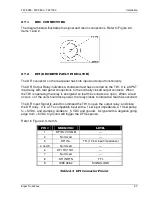
2.9 OUTPUT CONNECTIONS TO THE LOAD
2.9.1 TW 5250 OUTPUT CONNECTIONS
The Model TW 5250 can power 1-phase, 2-phase and 3-phase loads. Local or remote
sensing can be used. If local sense is desired, for best regulation, jumper Sense A to
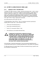
Output A, Sense B to Output B, etc. Outputs may be directly paralleled for greater
power. If the outputs are paralleled it is important to program the unit to the parallel
mode before shorting the outputs together (refer to Figure 2-4). Outputs cannot be
placed in series since the Neutral is common. However, by programming two phases
180° apart, double voltage, single phase is achieved.
Any phase sequence of wiring can be used.
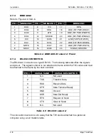
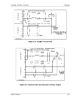
The sense Neutral is also common. Thus, it is important to wire the sense wires
properly (refer to Figure 2-5). If remote sense is used:
•
Sense A is connected to Power A;
•
Sense B is connected to Power B;
•
Sense C is connected to Power C; and
•
Neutral Sense is connected to Neutral Power.
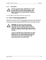
Output power neutral must be connected to chassis
ground for safe operation. The TW system is shipped with
a green/yellow wire connected from output power neutral
to chassis ground. It is important that the Neutral not be
> 20V away from the chassis potential; the unit will shut
down if this voltage is exceeded. For -101 units, the
Green/Yellow wire can be removed and the neutral can
float up to 156V away from chassis potential.
If a transformer or inductive load is present, the unit should be programmed to AC.
This prevents small amounts of DC being generated which may saturate the magnetics.
For best performance, the sense leads should be connected and output neutral should
be connected to chassis ground.


