TW 5250 • TW 3500 • TW 1750 Installation
Elgar TrueWave 2-15
In high performance applications, as in motor start-up and associated inrush/ transient
currents, additional consideration is required. The cable wire gauge must consider
peak voltages and currents that may be up to ten times the average values. An
underrated wire gauge adds losses that alter the inrush characteristics of the
application and thus the expected performance.
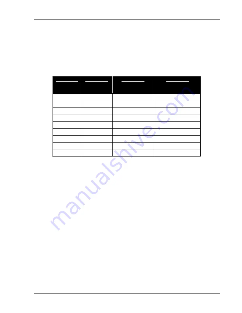
Table 2-8 identifies ratings for popular DC and AC power source cable wire gauges.
C
OLUMN
1:
SIZE
(AWG)
C
OLUMN
2:
AMPERES
(MAXIMUM)
C
OLUMN
3:
OHMS/100 FEET
(ONE WAY)
C
OLUMN
4:
IR DROP/100 FEET
(COL. 2 X COL. 3)
14
15
0.257
3.85
12
20
0.162
3.24
10
30
0.102
3.06
8
40
0.064
2.56
6
55
0.043
2.36
4
70
0.025
1.75
2
95
0.015
1.42
1/0
125
0.010
1.25
3/0
165
0.006
1.04
Table 2-8 Recommended Wire Gauge Selection Guide
The following notes apply to Table 2-8 and to the power cable definition:
1. The above figures are based upon insulated copper conductors at 25°C (77°F),
two current carrying conductors in the cable plus a safety (chassis) ground.
Columns 3 and 4 refer to “one way” ohms and IR drop of current carrying
conductors (e.g., a 50-foot cable contains 100 feet of current carrying
conductor).
2. Determine which wire gauge for the application by knowing the expected peak
load current (I
peak
), the maximum tolerated voltage loss (V
loss
) within the cable,
and the one way cable length.

