background image

TW 5250 • TW 3500 • TW 1750  Operation 

Elgar TrueWave  3-25 

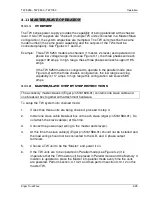
3.11 MASTER/SLAVE OPERATION 

3.11.1 OVERVIEW 

The TW series power supply provides the capability of being paralleled at the chassis 

level. If two TW supplies are “chained” (multiple TW units connected in a Master/Slave 

configuration), the system ampacities are multiplied. The TW units must be the same 

model number (the same power capability) and the outputs of the TWs must be 

connected properly. See Figures 3-1 and 3-2. 

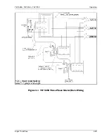
Example:  Three TW 5250 models are chained (1 master, 2 slaves) and operated in 3 

phase low voltage range mode (see Figure 3-1), the three phases will each 

support 39 amps. In high range, these three phases will each support 19.5 

amps. 

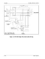
If the TW 5250 master is configured to operate in the parallel mode (see 

Figure 3-2) with the three chassis configuration, the low range sourcing 

capability is 117 amps. In high range this configuration will source 58.5 

amps.  

3.11.2 MASTER/SLAVE: STEP BY STEP INSTRUCTIONS 

The accessory master/slave kit (Elgar p/n 5161608-01) contains one slave cable and 

one breakout box together with attachment hardware. 

To setup the TW system into chained mode: 

1. If less than three units are being chained, proceed to step 3. 

2. Install one slave cable breakout box onto each slave (elgar p/n 5161583-01). Do 

not attach the slave cable(s) at this time. 

3. Connect the power input wiring to the master and slave(s). 

4. At this time the slave cable(s) (Elgar p/n 5161586-01) should not be installed and 

the load wiring should not be connected to the A,B, and C phase output 

terminals. 

5. Choose a TW unit to be the “Master” and power it on. 

6. If the TW units are to be operated in Parallel mode (see Figure 3-2) it is 

imperative that the TW master unit be placed in Parallel mode and the Memory 0 

location is updated to place the Master into parallel mode every time the units 

are powered. Perform section: 3.10.21 and then perform section 3.10.12 on this 

master TW. 


Summary of Contents for TW1750

Page 1: ...ct Fax 858 458 0267 Email Domestic Sales domorders sd ametek com International Sales intlorders sd ametek com Customer Service service ppd ametek com Web www programmablepower com TrueWave AC Power Source Models TW5250 TW3500 TW1750 Operation Manual March 2011 Document No M161469 01 Rev H ...

Page 2: ......

Page 3: ...ion purposes only Notice of Copyright TrueWave AC Power Source 2010 AMETEK Programmable Power Inc All rights reserved Exclusion for Documentation UNLESS SPECIFICALLY AGREED TO IN WRITING AMETEK PROGRAMMABLE POWER INC AMETEK a MAKES NO WARRANTY AS TO THE ACCURACY SUFFICIENCY OR SUITABILITY OF ANY TECHNICAL OR OTHER INFORMATION PROVIDED IN ITS MANUALS OR OTHER DOCUMENTATION b ASSUMES NO RESPONSIBILI...

Page 4: ...ii This page intentionally left blank ...

Page 5: ...onnel and equipment safety Always ensure that facility AC input power is de energized prior to connecting or disconnecting any cable In normal operation the operator does not have access to hazardous voltages within the chassis However depending on the user s application configuration HIGH VOLTAGES HAZARDOUS TO HUMAN SAFETY may be normally generated on the output terminals The customer user must e...

Page 6: ...e instructions of AMETEK is opened modified or disassembled in any way without AMETEK s consent or is used in combination with items articles or materials not authorized by AMETEK The Buyer may not assert any claim that the Products are not in conformity with any warranty until the Buyer has made all payments to AMETEK provided for in the Purchase Order Agreement PRODUCT RETURN PROCEDURE 1 Request...

Page 7: ...ction and Safety 1 6 1 8 Agency Requirements 1 7 1 9 Physical Specifications 1 7 1 10 Environmental Data 1 7 1 11 Other Standard Features 1 8 1 12 Options 1 9 SECTION 2 INSTALLATION 2 1 Introduction 2 1 2 2 Unpacking 2 1 2 3 Pre Installation Inspection 2 1 2 4 Installation 2 2 2 5 Air Intake and Exhaust 2 2 2 6 Installation Dimensional Drawings 2 3 2 7 Input Output Connectors 2 6 2 7 1 BNC Connect...

Page 8: ...ing Programmable Parameters 3 3 3 6 Menu System 3 5 3 7 Menu Tree 3 6 3 8 Menu Operations 3 7 3 8 1 Menu Prompts and Key Sequences 3 12 3 9 Password Protection 3 12 3 9 1 Creating the Password 3 12 3 9 2 Clearing the Password 3 13 3 10 Sample Menu Changes 3 13 3 10 1 Change TW GPIB Address 3 13 3 10 2 Set TW to Close Output Relay at Power Up 3 13 3 10 3 Place TW into Standby Mode After Power Up 3 ...

Page 9: ... 21 Place TW into Parallel Amplifiers Mode 3 23 3 10 22 Set Password 3 23 3 10 23 Clear Password 3 24 3 11 Master Slave Operation 3 25 3 11 1 Overview 3 25 3 11 2 Master Slave Step by Step Instructions 3 25 3 11 3 Return to Standalone Operation 3 28 APPENDIX A Fault Operations A 1 LIST OF TABLES Table 2 1 Recommended Mounting Slide 2 2 Table 2 2 TW Input Output Connectors 2 6 Table 2 3 DFI Connect...

Page 10: ...ure 2 1 Mounting Dimensions Front View 2 3 Figure 2 2 Mounting Dimensions Top and Side View 2 4 Figure 2 3 Rear Panel 2 5 Figure 2 4 Parallel Connections 2 13 Figure 2 5 Sense Lead Connections for 3 Phase Output 2 13 Figure 3 1 TW 5250 Three Phase Master Slave Wiring 3 29 Figure 3 2 TW 5250 Single Phase Master Slave Wiring 3 30 ...

Page 11: ...t No M161469 02 One to three phase AC sine wave or DC output is specified by pushbutton LED menu based control Incremental and absolute voltage and current setpoints are available at the TW front panel The TW incorporates a hierarchical menu system to set system parameters The TrueWave sources are true DC as well as AC power supplies Up to 312 VRMS are available in AC or AC DC modes Multi phase mo...

Page 12: ...ration 10 msec with PFC input configuration Frequency 47 to 63 Hz minimum 1 3 OUTPUT SPECIFICATIONS at 25ºC unless specified Calibration Interval 1 year Waveshape DC and sine Dropout Dropout of an integer number of cycles on any combination of phases at any phase angle and at any programmable frequency is possible via GPIB command Sub integer number of cycles can be achieved by varying the phase a...

Page 13: ...g Accuracy GPIB Front Panel 1 of full scale 0 5 of actual Current Programming Resolution GPIB Front panel 0 03 maximum 12 bits Current Stability in constant current mode 0 5 of setting after 10 minute warmup Inductive Output Impedance high range 104µh typical in low output impedance mode 796 5µh 2 in standard reference impedance mode Resistive Output Impedance high range 0 050Ω typical in low outp...

Page 14: ...se Programming Accuracy 1º maximum Phase Programming Resolution 0 1º minimum Overvoltage Protection Accuracy 1 of full scale 1 of actual maximum peak voltage Overvoltage Protection Range 116 of rated output Overvoltage Protection Response Time 0 1 msec maximum Overcurrent Protection Accuracy 1 of full scale 1 of reading maximum Overcurrent Protection Range 115 of rated output Overcurrent Protectio...

Page 15: ... 200VA Frequency Accuracy 0 25 of reading Output Phase Accuracy 0 5 Output Phase Resolution 0 3 1 5 GPIB AND RS 232 READBACK Output Voltage Accuracy 0 3 of full scale 0 2 of reading maximum Output Voltage Resolution 0 1 VRMS maximum Output Current Accuracy 0 3 of full scale 0 5 of reading maximum Output Current Resolution 0 01 Amps RMS maximum Output Power Range 0 to 1900 W per phase minimum Outpu...

Page 16: ...hases Crest Factor of Load Calculated from 1 or 3 Phases Output Phase B and C Relative to Phase A 1 7 PROTECTION AND SAFETY Overvoltage Shutdown Programmable for 15V to 255V peak 156V range 30V to 510V peak 312V range Undervoltage Shutdown Automatic not programmable Programmable Current Limit Shutdown Can be set to 1 of range 0 5A to 13A for 156V range 0 5A to 6 5A for 312V range Programmable Curr...

Page 17: ...s 28 kg Cooling Air is drawn in from the front top and sides and exhausted through the rear of the chassis 1 10 ENVIRONMENTAL DATA Operating Temperature 0 C to 45 C 32 F to 113 F Note temperature measured at air inlet of TW If cabinet mounted cabinet inlet air may be rated at lower maximum temperature due to warming of inlet air Storage Temperature 40 C to 70 C 40 F to 158 F Humidity Non condensin...

Page 18: ...is at 0 30 µs LOCK locks output to input TTL frequency signal needs to supply pull down current of 15 mA with voltage drop of 0 6V no pull up needed Negative edge is at 0 30 µs LOCK Specifications Frequency range is 40 00 Hz to 500 00 Hz Tracking range is 10 of programmed center frequency Duty cycle is 50 10 Slew rate is 02 of input frequency second maximum which produces a maximum phase shift of ...

Page 19: ...2 of full scale output External Gain Control 0 to 7 07 VDC provides zero to full scale programmed voltage output 2 of full scale output External Input Impedance 10 kΩ System Firmware System firmware is stored in flash memory This makes it possible to upgrade the firmware without disassembling or returning the unit 1 12 OPTIONS Parallelable for Additional Power above 5250 VA requires accessory atta...

Page 20: ...General Description TW 5250 TW 3500 TW 1750 1 10 Elgar TrueWave This page intentionally left blank ...

Page 21: ...scription of the damage should be noted on the carrier s receipt and signed by the driver of the carrier agent If damage is not apparent until the instrument is unpacked a claim for concealed damage should be placed with the carrier In addition the shipping container s and filler material should be saved for inspection Forward a report of damage to the Elgar Service Department Elgar will provide i...

Page 22: ...ates over 2250W with the PFC option It is important that the heat produced is properly vented to the exterior of the chassis Special baffling to control air flow may be required to prevent hot exhaust air being drawn into the intakes if the unit is to be run continuously at full power The preferred mounting method for full power operation is bottom mounting Slide mounting may impair airflow from t...

Page 23: ... Refer to Figure 2 1 and Figure 2 2 for information on outline and mounting dimensions of the unit Refer to Figure 2 3 and Table 2 2 through Table 2 5 for information on rear panel connectors Also refer to Figure 2 2 for customer wiring conduit details Figure 2 1 Mounting Dimensions Front View ...

Page 24: ...Installation TW 5250 TW 3500 TW 1750 2 4 Elgar TrueWave Figure 2 2 Mounting Dimensions Top and Side View ...

Page 25: ...TW 5250 TW 3500 TW 1750 Installation Elgar TrueWave 2 5 Figure 2 3 Rear Panel ...

Page 26: ...1 7 SLAVE 37 POS SUB D FEMALE ITT CANNON PN ADC37SOL2 8 AUX OUT 4 POS MINIFIT JR MOLEX PN 39 29 9045 9 OUTPUT POWER TERMINAL BARRIER 6 POS 6 HDW MAGNUM PN A304106 07 CA MP8 10 REMOTE SENSE TERMINAL BARRIER 6 POS 6 HDW MAGNUM PN A304106 07 CA MP8 Refer to Table 2 6 and Table 2 7 for Fuse Ampere Rating PHASE A FUSE F1 480VAC 50A TIME DELAY BUSSMAN SC50 LITTLEFUSE SLC50 ELGAR PART 858 501 50 11 PHASE...

Page 27: ... relay is energized so that the contacts are open When a fault occurs or if the unit should lose power the relay closes to indicate a fault has occurred The DFI Input Signal is used to command the TW to open the output relay and close the DFI relay It is a TTL compatible input with a 1 kΩ input impedance a 10 kΩ pullup to 5 VDC and clamping diodes to _5 VDC and ground A signal with a negative goin...

Page 28: ...2 4 IEEE 488 2 Connector Pinout 2 7 4 RS 232 CONNECTOR The RS 232 C connector is a type DB 15S The following table identifies the signals and pinout The signal common is not attached to frame within the TW series and must be attached to the frame by the host controller PIN SIGNAL NAME SIGNAL DESCRIPTION 1 N C Not used 2 TXD Transmit Data 3 RXD Receive Data 4 DTR Data Terminal Ready 5 GND Ground 6 ...

Page 29: ...t current values If it is required to shut the unit power off using the front panel power switch please wait at least 30 seconds before re applying power WARNING An overcurrent protection device i e circuit breaker is required in the building installation The circuit breaker should be rated for continuous current as required by the TW system see Table 2 2 Installation should comply with local safe...

Page 30: ...SA 13A RMS Not Required 20A 20A RMS RECT INTL 13A RMS 23A RMS 20A 20A RMS Table 2 6 Input Currents for 3 Phase Input Power REQ D INPUT TERMINAL JUMPER CONNECTIONS CONNECT 1 PHASE INPUT POWER TO VOLTAGE MAXIMUM INPUT CURRENT F1 F3 FUSE RATING RECOMMENDED CIRCUIT BREAKER RATING MAX TW 5250 PFC USA F1 to F2 F1 F3 187 264 VRMS L L 28A RMS 40A 40A RMS PFC INTL F1 to F2 F2 to F3 F1 Neutral 187 264 VRMS ...

Page 31: ...ll operate at this voltage CAUTION For units built before June 2004 the Neutral must not be broken by an external switch Severe damage to the unit may occur if Neutral is broken and phase voltage is present Connect the input wires to phases A F1 B F2 C F3 and Neutral Ensure that the chassis safety ground is also connected Use cables with ratings equal to or greater than the current rating listed o...

Page 32: ...us it is important to wire the sense wires properly refer to Figure 2 5 If remote sense is used Sense A is connected to Power A Sense B is connected to Power B Sense C is connected to Power C and Neutral Sense is connected to Neutral Power Output power neutral must be connected to chassis ground for safe operation The TW system is shipped with a green yellow wire connected from output power neutra...

Page 33: ...TW 5250 TW 3500 TW 1750 Installation Elgar TrueWave 2 13 Figure 2 4 Parallel Connections Figure 2 5 Sense Lead Connections for 3 Phase Output ...

Page 34: ... up to 450 Hz power cabling The same engineering rules apply whether going into or out of an electrical device Thus this guide applies equally to the input cable and output cable for this Elgar instrument and application loads Power cables must be able to safely carry maximum load current without overheating or causing insulation destruction It is important to everyday performance to minimize IR v...

Page 35: ...4 IR DROP 100 FEET COL 2 X COL 3 14 15 0 257 3 85 12 20 0 162 3 24 10 30 0 102 3 06 8 40 0 064 2 56 6 55 0 043 2 36 4 70 0 025 1 75 2 95 0 015 1 42 1 0 125 0 010 1 25 3 0 165 0 006 1 04 Table 2 8 Recommended Wire Gauge Selection Guide The following notes apply to Table 2 8 and to the power cable definition 1 The above figures are based upon insulated copper conductors at 25 C 77 F two current carr...

Page 36: ...20 ampere Ipeak circuit which may have a maximum 0 5 volt drop Vloss along its 15 foot cable one way cable length requires by formula a Column 3 resistance value of 0 083 This corresponds to wire gauge size 8 AWG If the cable length was 10 feet the Column 3 value would be 0 125 and the corresponding wire gauge would be 10 AWG 3 Aluminum wire is not recommended due to soft metal migration at the te...

Page 37: ...nductors from any source The differential voltage to other nearby conductors and Safety margins to accommodate degradations due to age mechanical abrasion and insulation migration caused by bending and temperature 7 As frequency increases the magnetic field of the current carrying conductors becomes more significant in terms of adverse coupling to adjacent electrical circuits Use twisted pairs to ...

Page 38: ...Installation TW 5250 TW 3500 TW 1750 2 18 Elgar TrueWave This page intentionally left blank ...

Page 39: ...of TW all phases Present voltage range 0 156V 0 312V Output relay state the output relay must be closed to source current 3 2 MENU PARAMETERS The following parameters are programmed by means of the optionally password protected front panel menu system GPIB address Over current Foldback Shutdown Timeout modes Coupling to AC DC or AC DC Parallel mode On Off EXT connector to Direct Gain or no control...

Page 40: ...r or using the arrow keys to ramp a given parameter up or down in variable step sizes For instance you can step the voltage in units of 100 s 10 s 1 s or tenths of a volt using the arrow keys The longer the arrow is held the faster the specified value increases or decreases To quickly source voltage to the TW output terminals set phase A current limit and set phase A voltage to a given value by en...

Page 41: ...ower Factor calculated on the presently displayed phase appears in the right position of the display If the TW is not in parallel mode and there is more than one amplifier installed the ABC spinner can be set to AB or ABC and the total Power Factor is displayed on the right readout When the I key is pressed and the CF LED lights up the Crest Factor calculated on the presently displayed phase appea...

Page 42: ... Up arrow will increment the number if the change doesn t push the number out of range The setpoint will be changed and the output will be affected immediately NOTE When using arrow keys to adjust a programming value up or down the change made is immediate and final The output will reflect the changes In program mode use the number keys to specify an absolute value If any program key is pressed af...

Page 43: ...e The menu operations are executed by pressing either the Up arrow or the Down arrow from a front panel readback state the Program LEDs must not be lit It is assumed here that the password is not set If you hesitate too long in a given menu display without pressing a key the menu system will time out and the readback display will re appear Typically where a Right arrow is specified a Left arrow al...

Page 44: ...r generation parameters of the TW CURRENT TYPE SHUT FOLD CURR SHUT CURR FOLD SET DELAY 200 COUPLING AC DC AC DC COUP AC COUP DC COUP AC DC PARALLEL OFF ON PAR OFF PAR ON BNC SYNC TRIG O PH A I PH A O TRIG I TRIG OUT PHASE A OUT PHASE A IN TRIG IN CONTROL OFF DIR GAIN CONT OFF CONT DIRECT CONT GAIN SENSE LOCAL DIST SENSE LOCAL SENSE DISTANT CHASSIS CHAS QTY 1 CHAIN CHAIN QTY 1 IEC SETTING ON OFF IE...

Page 45: ...TER TO CLEAR SET CODE oooo REPEAT oooo PROG FRT ENA DIS PROG FRT ENA PROG FRT DIS 3 8 MENU OPERATIONS SYST SELF TEST Press ENT to perform a self diagnostic test the result is displayed as PASSED or FAILED PORT The communications parameters are set here GPIB ADDR FACTORY 25 The GPIB address can be set here to address 1 31 CONFIG CURRENT The over current mode and timing are set here TYPE The current...

Page 46: ...ource DC voltage COUP AC DC Specify that the amp s will source AC with a bi polar DC offset PARALLEL default Off The TW is capable of operating all installed amplifiers in parallel thereby increasing the single phase VA of the box The TW is controlled by the A phase alone when in parallel mode PAR OFF Set parallel off mode independently controllable amps front panel ABC spinner operational PAR ON ...

Page 47: ...CONT GAIN This setting allows a control voltage of 5Vrms 7 07 Vpeak to scale the output waveform 0 Full Scale Output SENSE The amplifier sense point is either external remote distant or internal local and is adjustable here LOCAL The amplifiers are controlled independent of the external sense lines DISTANT default The amplifiers are controlled via the external sense lines feedback CHASSIS The chas...

Page 48: ...setup to locations 0 98 The following program data are saved and restored A B C volt setpoints A B C current limit setpoints A B C offset volt setpoints Voltage Range High Low B phase angle C phase angle setpoints Frequency setpoint Current type Shut Fold Current limit timeout Coupling type AC DC ACDC Parallel mode On Off of internal amplifiers Clock Lock Sync mode SyncOut RefOut RefIn TrigIn Aux ...

Page 49: ...4 Sense Remote 15 Internal Amplifiers Parallel Mode Off 16 Voltage Range Low 17 Chassis Quantity 1 18 A Volt Limit 156 0 19 B Volt Limit 156 0 20 C Volt Limit 156 0 21 Phase Angle A 0 0 22 Phase Angle AB 120 0 23 Phase Angle AC 240 0 24 Clk Lock Sync Phase A Out 25 Aux Input Off 26 IEC Load State Normal STARTUP At power up the TW either will automatically source voltage to the output or it will wa...

Page 50: ...ategory that supports various forms e g see Config category use the Left and Right arrow keys to quickly change the possible modes without dropping to the sub categories After making any changes inside the menu system repeatedly press the ABC BACK key to back out of the menu and save your changes If the menu system is allowed to time out the changes made will be lost 3 9 PASSWORD PROTECTION 3 9 1 ...

Page 51: ...s the Up arrow key until the display reads SYST Press the ENT key Press the Up arrow key The display will read PORT Press the ENT key If the present GPIB address is 25 the display will read GPIB ADDR 25 Either enter the new address using the 0 9 keys and press ENT or press the Left arrow or the Right arrow key to specify the new value for the GPIB address Press ABC BACK repeatedly to back out of m...

Page 52: ... program keys are disabled the Output key and Prog keys VOLTAGE FREQUENCY PHASE and CURRENT POWER are all non operable In this mode the TW will perform as last saved to system memory 0 and also can be controlled via the SCPI interface Press the Up arrow key until the display reads ACCESS Press the ENT key Assuming the password is not set the display will read CODE NOT SET Press the Up arrow key Th...

Page 53: ...G FRT ENA Press the ENT key The display will read PROG FRT ENA Press ABC BACK repeatedly to back out of menus and return to readback display mode The Output and Prog keys are again operable 3 10 6 PLACE TW INTO DC MODE Press the Up arrow key until the display reads CONFIG Press the ENT key Press the Up arrow key until the display reads COUPLING AC or COUPLING AC DC Press the Right arrow key until ...

Page 54: ...ss the ENT key The display will read COUP AC DC Press ABC BACK repeatedly to back out of menus and return to readback display mode 3 10 8 PLACE TW INTO AC MODE Press the Up arrow key until the display reads CONFIG Press the ENT key Press the Up arrow key until the display reads COUPLING DC or COUPLING ACDC Press the Right arrow key until the display reads COUPLING AC Press the ENT key The display ...

Page 55: ... ENT key The display will read CURR FOLD Press ABC BACK repeatedly to back out of menus and return to readback display mode 3 10 10 SET TW INTO CURRENT SHUTDOWN MODE Press the Up arrow key until the display reads CONFIG Press the ENT key Press the Up arrow key until the display reads CURRENT Press the ENT key The display will read TYPE FOLD Press the Right arrow key The display will read TYPE SHUT...

Page 56: ...w value in the 0 9 keys followed by the ENT key or use the Left arrow or Right arrow key to decrement increment the timeout value followed by the ENT key Press ABC BACK repeatedly to back out of menus and return to readback display mode 3 10 12 STORE A MACHINE STATE Press the Up arrow key until the display reads STORAGE Press the ENT key The display reads STORE 0 Either enter a new value in the 0 ...

Page 57: ...he Left arrow or Right arrow key to decrement increment the value followed by the ENT key Press ABC BACK repeatedly to back out of menus and return to readback display mode 3 10 14 RECALL FACTORY CONFIGURATION Press the Up arrow key until the display reads STORAGE Press the ENT key The display reads STORE 0 Press the Up arrow key The display reads RECALL 0 Enter key 9 twice 99 followed by the ENT ...

Page 58: ...s the ENT key The display reads SENSE LOCAL Press ABC BACK repeatedly to back out of menus and return to readback display mode 3 10 16 SPECIFY REMOTE SENSE Press the Up arrow key until the display reads CONFIG Press the ENT key Press the Up arrow key until the display reads SENSE LOCAL Press the Right arrow key The display will read SENSE DIST Press the ENT key The display reads SENSE DISTANT Pres...

Page 59: ...e display reads PHASE A IN Press ABC BACK repeatedly to back out of menus and return to readback display mode 3 10 18 PROGRAM SYNC CONNECTOR TO SEND A PULSE AT PHASE A ZERO CROSSING Press the Up arrow key until the display reads CONFIG Press the ENT key Press the Up arrow key until the display reads BNC Press the ENT key Assuming the TW is in Trigger pulse out mode the display reads SYNC TRIG O Pr...

Page 60: ...eads CONTROL GAIN Press the ENT key The display reads CONT GAIN Press ABC BACK repeatedly to back out of menus and return to readback display mode 3 10 20 SPECIFY TW INSTALLED AMPS QTY Press the Up arrow key until the display reads CONFIG Press the ENT key Press the Down arrow key until the display reads INSTALLED Press the ENT key Assuming that 1 amplifier is presently installed the display reads...

Page 61: ...ey The display will read PAR ON Press ABC BACK repeatedly to back out of menus and return to readback display mode 3 10 22 SET PASSWORD Press the Up arrow key until the display reads ACCESS Press the ENT key Display will read CODE NOT SET Press the ENT key Display will read CLEAR Press the Up arrow key The display will read SET NOT SET Press the ENT key The display will read CODE oooo Press your d...

Page 62: ...atedly to back out of menus and return to readback display mode 3 10 23 CLEAR PASSWORD Press the Up arrow key until the display reads ACCESS Press the ENT key Display will read CODE SET Press the ENT key Display will read CLEAR Press the ENT key The display will read ENTER TO CLEAR Press the ENT key The display will read CLEAR Press ABC BACK repeatedly to back out of menus and return to readback d...

Page 63: ...ps In high range this configuration will source 58 5 amps 3 11 2 MASTER SLAVE STEP BY STEP INSTRUCTIONS The accessory master slave kit Elgar p n 5161608 01 contains one slave cable and one breakout box together with attachment hardware To setup the TW system into chained mode 1 If less than three units are being chained proceed to step 3 2 Install one slave cable breakout box onto each slave elgar...

Page 64: ...two slaves set chassis number to 3 Press the ABC Back key until the TW reads SYS RESTART and the TW will automatically reboot 8 Now turn off the master TW while it reads Sys Restart or while it is searching for slaves 9 Turn on the next slave TW 10 Place the first slave TW into slave mode by either setting the chain address in the menu system or through the SCPI system SCPI GPIB Send to the slave ...

Page 65: ...long as the slave s and the master are ultimately all connected together in some manner 17 Connect the GPIB or RS232 control line to the master As soon as a slave is connected and talking with it s master there will be no menu RS232 or GPIB operations available on the slave 18 If DFI connectors are being used for systems protection connect the DFI daisy chain through the master and all slaves 19 F...

Page 66: ...LONE OPERATION To return the TW system to standalone mode 1 Power down all connected units 2 Remove Master Slave cables The steel housings may remain on the back of the slave TW units if they were originally installed 3 Disconnect any bussed power wiring from the TW outputs 4 Power up TW units 5 If the message Rcl Curr High appears on the display of any of the units this is merely to notify the us...

Page 67: ...TW 5250 TW 3500 TW 1750 Operation Elgar TrueWave 3 29 Figure 3 1 TW 5250 Three Phase Master Slave Wiring ...

Page 68: ...Operation TW 5250 TW 3500 TW 1750 3 30 Elgar TrueWave Figure 3 2 TW 5250 Single Phase Master Slave Wiring ...

Page 69: ...t a run time recoverable error The TW power should be cycled If this error appears excessively consult the Elgar technical support staff PS A FAULT 0 PHASE OVER VOLTAGE ERROR This error is reported when a given Phase experiences an over voltage condition This error is a run time recoverable error From the front panel press the ENTER key Through SCPI send the RST command PS A FAULT 1 PHASE OVER CUR...

Page 70: ...coverable error The TW power should be cycled If this error appears excessively consult the Elgar technical support staff SELF TEST FAULT This error will occur if 1 The amplifier installed quantity is incorrect in the Menu system Perform section 3 10 20 CONFIG INSTALLED should be set to 1 if the TW has one amplifier installed 1750 2 if the TW has two amplifiers installed 3500 3 if the TW has 3 amp...

Reviews: