background image

Operation


Page 18 of 32


FUTURE

SAFE


5.2


Adjustment Options 

The FutureSafe offers the following options to adjust it cor-

rectly to suit every situation: 


Pivoting the swivel arms (see Section 5.2.1, page 18), 


Lengthening and shortening the swivel arms (see Sec-

tion 5.2.2, page 19), 


Adjusting the height of the head- and backrest (see 

Section 5.2.3, page 20) and  


Moving the FutureSafe forwards or backwards (only ap-

plies to FutureSafe with side anchorage plate, see Sec-

tion 5.2.4, page 21). 

5.2.1


Pivoting the swivel arms 

The interior of the vehicle can be put to optimum use, to 

transport goods or passengers who are not in a wheel-

chair, when the swivel arms are pivoted away to the side 

of the vehicle. The swivel arms are pivoted out of the vehi-

cle in order to load a wheelchair-bound passenger. When 

driving the vehicle with a wheelchair-bound passenger on 

board, the swivel arms are adjusted such that the head- 

and backrest are located directly behind the passenger. 


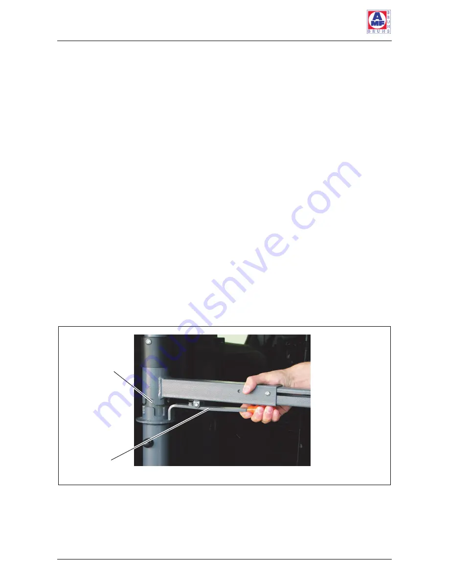
Figure 4: Pivoting the Swivel Arms 


Pull the operating lever of a swivel arm upwards, so that 

it lifts out of the latch (see Figure 4). 


Pivot the swivel arm by 90° or 180° to the desired posi-

tion. 

Latch 

Operating 

lever 

Summary of Contents for FUTURESAFE

Page 1: ...Operating Instructions FUTURESAFE www amf bruns de...

Page 2: ......

Page 3: ...ll the FutureSafe hand these Operating Instructions over to the new owner All details figures and dimensions contained in these Op erating Instructions are without obligation No claims in any form can...

Page 4: ...will lead to serious or fatal injuries if not avoided WARNING warns of a potentially dangerous situation which will lead to serious or fatal injuries if not avoided CAUTION warns of a potentially dan...

Page 5: ...rpose These are identified as follows Lists Instructional text e g a sequence of activities 3 Meaning of directions If directions are given in the text in front of front behind rear right left these d...

Page 6: ...1 4 Diagonal shoulder safety belt 14 2 1 5 Rating Plate 15 2 2 Technical Data 15 3 Transportation 16 4 Installation Commissioning 16 5 Operation 17 5 1 Safety Regulations for Operation 17 5 2 Adjustme...

Page 7: ...tions for Maintenance and Repair 25 6 2 Routine Maintenance Work 26 6 2 1 Maintenance schedule 26 6 2 2 Maintenance record 26 6 3 Maintenance and Inspection Record 26 7 De Commissioning and Conservati...

Page 8: ...a tion of the FutureSafe is a thorough knowledge of the ap plicable safety information and the safety regulations It is therefore imperative that this Chapter is read thor oughly before operating the...

Page 9: ...the FutureSafe for the purpose for which it was intended Always adhere to information given in these Operating Instructions Do not use the FutureSafe for any other purposes par ticularly those given i...

Page 10: ...ning maintenance repair fault finding and disposal of the FutureSafe must only be carried out by persons with the corresponding technical training and experience 1 4 Product Monitoring Please contact...

Page 11: ...tion of the FutureSafe under all operating conditions by providing instruction courses Proper use of the FutureSafe also includes adherence to the specified maintenance and repair work in particular s...

Page 12: ...vel arms the head and backrest The diagonal shoulder safety belt The aim of this chapter is to illustrate the construction and function of the FutureSafe To this end the individual as semblies and com...

Page 13: ...ly components see Figure 1 page 12 A side anchorage plate is particularly suitable for minibuses see Figure 2 The FutureSafe can be moved to the for wards or backwards in the vehicle by mounting it on...

Page 14: ...backrest are hung on the swivel arms They are each provided with mechanics for adjusting the height The backrest has a slanting profile This makes it possible to adjust the distance of the backrest t...

Page 15: ...e floor or side an chorage plate Figure 3 Rating Plate 2 2 Technical Data Designation FutureSafe Weight with anchorage plate 23 kg Weight with side anchorage plate 19 kg NOTE Remember to take the weig...

Page 16: ...of danger through incorrect installation A number of risks of personal injury and material damage can be caused if the FutureSafe is incorrectly installed in the vehicle Such risks of danger can not...

Page 17: ...d or passenger is are not correctly re strained in the vehicle the passenger in the wheelchair can suffer serious injury in an emergency braking situation or light road traffic collision Therefore Alw...

Page 18: ...voting the swivel arms The interior of the vehicle can be put to optimum use to transport goods or passengers who are not in a wheel chair when the swivel arms are pivoted away to the side of the vehi...

Page 19: ...es that hold the head and backrest in certain positions when pulled out or pushed in The swivel arms can be pushed in or pulled out without further preparations in order to adjust the head and backres...

Page 20: ...ssible safety by adjusting them to the correct height Figure 6 Adjusting the Height Press the latch button on the head or backrest and hold it pressed see Figure 6 Adjust the head or backrest up or do...

Page 21: ...securing screws by turning the black star grips Figure 7 Adjusting on Smartfloor Rails Push the FutureSafe forwards or backwards to the de sired position Turn the red locking levers back to the horiz...

Page 22: ...ch to engage see Section 5 2 1 page 18 Adjust the length of the swivel arm such that the backrest is positioned in the centre of the passenger s back see Section 5 2 2 page 19 Adjust the backrest forw...

Page 23: ...the same height as the top of the passen ger s head see Section 5 2 3 page 20 Figure 8 Optimum Adjustment of the FutureSafe NOTE Remember that the FutureSafe adjustment described here represents the i...

Page 24: ...r can present a source of danger in themselves Therefore Do not lay the lap belt over the armrests of the wheel chair Make sure that the lap belt lies across the lap of the passenger If the belt does...

Page 25: ...an accident If in doubt contact the customer service department for advice on whether it is safe to use the FutureSafe if it was only involved in a minor accident see Chapter 10 page 30 WARNING Risk o...

Page 26: ...Interval Activity Before use Carry out a visual inspection for damage or faults Initiate repairs if necessary 6 2 2 Maintenance record Enter maintenance and repair work that has been carried out into...

Page 27: ...following troubleshooting table Contact the customer service department if faults are encountered which cannot be remedied using the information and measures given in the table Fault possible Cause Re...

Page 28: ...Spare parts Page 28 of 32 FUTURESAFE 9 Spare parts Figure Designation Article No Headrest 200235904 Backrest 200235889 Belt H350225 Guide bushing 200249429...

Page 29: ...Spare parts FUTURESAFE Page 29 of 32 Figure Designation Article No Latch bushing 200249725 Protective cap SW17 10008439 Plastic grip orange 10010646...

Page 30: ...and help with general problems or queries The address is AMF Bruns GmbH Co KG Hauptstra e 101 D 26689 Apen Tel 49 0 44 89 72 72 30 Fax 49 0 44 89 62 45 service hubmatik amf bruns de www amf bruns de N...

Page 31: ......

Page 32: ...Art No 10019422 06 2017 Reg No Q1 0105027 AMF Bruns GmbH Co KG Hauptstra e 101 26689 Apen Telephone 49 0 4489 72 72 30 Fax 49 0 4489 62 45 service hubmatik amf bruns de www amf bruns de...

Reviews: