background image

Description


Linear Lift AL1


Page 13 of 72 

2


Description 

Persons who are wheelchair-bound can be embarked into or 

disembarked from a vehicle using the linear lift. 

The main components of the linear lift are: 

y


the platform, 

y


the lifting unit with carrier arms, guardrails and floor anchorages, 

y


the hydraulic system and 

y


the operating controls. 

The aim of this chapter is to illustrate the construction and function 

of the linear lift. To this end, the individual assemblies and compo-

nents are described in the following sections. 

2.1


Layout and Function 


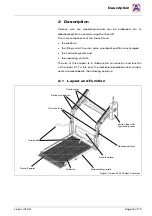
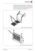
Figure 1: linear lift AL1 Solid, Overview


Guardrails


Platform


Roll-off guard


Switch box with 
hydraulic pump


Transfer plate


Carrier arms


Blinkers (optional)


Carrier struts


Remote control


Side roll-off guards


Summary of Contents for LINEARLIFT AL1

Page 1: ...Operating Instructions www amf bruns de LINEAR LIFT AL1 ...

Page 2: ......

Page 3: ...tion of the linear lift If you sell the linear lift hand these Operating Instructions over to the new owner All details figures and dimensions contained in these Operating In structions are non binding No claims in any form can be derived from these This document must not be reproduced or duplicated in full or in part without the prior written permission of the manufacturer The linear lift must ne...

Page 4: ...otentially dangerous situation which will lead to se vere or fatal injuries if not avoided CAUTION y warns of a potentially dangerous situation which will lead to slight or minor injuries or material damage if not avoided ATTENTION warns of a potentially dangerous situation which can cause mate rial damage if not avoided contains general notes and useful information gives a reference to important ...

Page 5: ...ord Linear Lift AL1 Page 5 of 72 3 Meaning of directions If directions are given in the text in front of front behind rear right left these directions relate to the normal direction of travel of the vehicle ...

Page 6: ...ls 19 3 Transportation 21 4 Installation Commissioning 21 5 Operation 22 5 1 Safety Regulations for Operation 22 5 2 Switching OFF in an Emergency Emergency Stop 24 5 3 Switching the linear lift ON 24 5 4 Switching the linear lift OFF 24 5 5 Lowering the Platform 25 5 6 Raising the Platform 27 6 Emergency Mode 30 6 1 Raising in the Emergency Mode 30 6 2 Lowering in the Emergency Mode 32 7 Maintena...

Page 7: ... Guard 42 11 2 Transfer Plate 43 11 3 Split Platform Adjusting the Platform Segments 44 11 4 Elbow Joints 45 11 5 Adjusting the Panorama Platform 48 11 6 Arrester Hooks 50 11 7 Micro Switches 51 12 Inspection Log 56 12 1 Inspection Log Master Data Sheet 57 12 2 Inspection List 58 12 3 Inspection Results 59 13 Electrical Circuit Diagrams 67 14 Hydraulic Circuit Diagram 69 15 Customer Service 70 16 ...

Page 8: ...hat the instructions and warnings herein are strictly observed The safety information and warnings given at the appropriate places in the following Chapters must also be strictly observed The manufacturer will not be held responsible if safety information and warnings are not observed In addition to the information given in these Operating Instructions local legislative regulations must be taken i...

Page 9: ...ring persons who are not seated in a wheelchair y it is used as a link bridge or y it is used by incompetent persons 1 3 Personnel Requirements The linear lift must only be handled by persons who y who are of legal age y have been instructed in how to operate the linear lift y have read and understood these Operating Instructions y have proven their ability to operate the linear lift to the vehicl...

Page 10: ... If damage occurs AMF Bruns GmbH Co KG will require the serial number the year built as well as a description of the damage and if possible a photograph of the damage 1 5 Danger Zone The danger zone is any area on below or within the range of mo vement of the platform as well as around the drive and carrier sys tem in which persons are exposed to the risk of injury or damage to health CAUTION Risk...

Page 11: ...ive devices are correctly fitted see Section 1 6 page 11 Such de vices must only be removed in order to enable maintenance and repair work to be carried out All safety and protective devices must be replaced immediately after such work has been comple ted If they are not replaced correctly there is a high risk of injury y The linear lift must only be used for the purpose for which it is in tended ...

Page 12: ...l expert at intervals of not more than 1 year after commissioning During inspection faults affecting the safety should be systematically identified and remedial action ta ken see Inspection Log page 56 y Do not deposit any items on the linear lift Persons can suffer inju ries if such items fall off the platform y The linear lift must not be operated in a faulty condition as seri ous injuries may b...

Page 13: ...or anchorages y the hydraulic system and y the operating controls The aim of this chapter is to illustrate the construction and function of the linear lift To this end the individual assemblies and compo nents are described in the following sections 2 1 Layout and Function Figure 1 linear lift AL1 Solid Overview Guardrails Platform Roll off guard Switch box with hydraulic pump Transfer plate Carri...

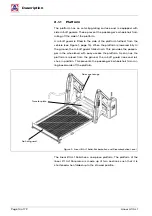
Page 14: ...roll off guard folds down This provides the passen ger in the wheelchair with easy access the platform As soon as the platform is raised from the ground the roll off guard rises and lat ches in position This prevents the passenger s wheelchair from rol ling backwards off the platform Figure 2 linear lift AL1 Solid Embarkation and Disembarkation Level The linear lift AL1 Solid has a one piece platf...

Page 15: ...ior height In addition to this the driver has a clear view through the rear window when driving Over and above this the fact that a linear lift is installed in the vehicle can not be seen from the outside see Figure 3 and Figure 4 Figure 3 linear lift AL1 Panorama Overview Figure 4 linear lift AL1 Panorama Stowed Position Platform Platform ...

Page 16: ...ark level the transfer plate closes the gap between platform and vehicle This ensures convenient safe embarkation disembar kation see Figure 1 page 13 and Figure 2 page 14 2 1 3 Lifting unit The lifting unit represents the connection between platform and ve hicle The lifting and lowering movements are carried out by four carrier arms that are powered by hydraulic cylinders see Figure 1 page 13 The...

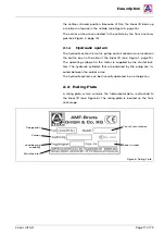
Page 17: ...ch box on the side of the linear lift see Figure 1 page 13 The operating voltage for the motor is supplied by the starter bat tery The hydraulic cylinders that are powered by the pump are lo cated between the carrier arms The hydraulic system can be manually operated in an emergency 2 2 Rating Plate A rating plate which contains the fundamental data is attached to the linear lift see Figure 6 The ...

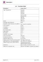
Page 18: ...g speed 0 058 m Max lowering speed 0 068 m Deploy speed 0 3 m Stow speed 0 3 m Operating control voltage 12 V Current consumption max 60 A Sound pressure emission 78 dB A Equipment suitable for use in the vehicle Safeguard against the platform lowering inadver tently if leaks occur in the hydraulic pipelines Burst pipe protection valve see Hydraulic Circuit Diagram Safeguard against excess hydraul...

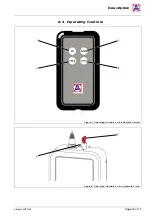
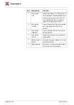
Page 19: ...Description Linear Lift AL1 Page 19 of 72 2 4 Operating Controls Figure 7 Operating Controls on the Remote Control Figure 8 Operating Controls on the Hydraulic Pump 3 2 5 1 4 6 ...

Page 20: ...a longer period of time 2 Push button DOWN Lowers the platform from the embarka tion disembarkation level to the ground 3 Push button UNFOLD Lowers the linear lift from the vertical stowed position 4 Push button FOLD Raises the linear lift to the vertical sto wed position 5 Battery isolation switch Interrupts the power supply to the hyd raulic pump motor 6 Circuit breaker Trips when a fault occurs...

Page 21: ...damage can be caused if the linear lift is incorrectly installed in the vehicle Such risks can not only occur during installation but also as a result of installation not being carried out correctly Therefore y The linear lift must only be installed in the vehicle by trained spe cialist personnel This also applies to the electrical connections y The vehicle manufacturer s body fitting guidelines m...

Page 22: ... Risk of injury through falling from the platform Persons who are not seated in a wheelchair can fall off the platform There is a risk of injury Therefore y It is forbidden for persons to ride on the platform id they are not in a wheelchair WARNING Risk of injury and material damage if the linear lift is operated by un authorised persons Dangerous operating conditions may be caused if the linear l...

Page 23: ... of move ment of the platform y Always stand at an adequately safe distance from the platform during operation y Inform other persons of the danger y Keep the danger zone under observation and stop the linear lift if any persons enter the danger zone WARNING Risk of injury if protective and safety devices are removed or are de fective If protective and safety devices are modified bypassed or remov...

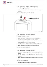
Page 24: ...en operating the linear lift make certain that the door can not swing closed due to wind or other influences Insert the key into the battery isolation switch 5 see Figure 9 Switch the linear lift ON at the battery isolation switch 5 The linear lift is ready for operation 5 4 Switching the linear lift OFF Accompany the passenger who is still on the platform off the platform Run the platform to the ...

Page 25: ... fold down to the horizontal position and are lowered until the platform has reached the embarkation disembar kation position The linear lift stops automatically in this position Release the UNFOLD push button 3 on the remote control Replace the remote control to its holder Accompany a passenger out of the vehicle and onto the platform for a disembarkation procedure Make sure that the centre of gr...

Page 26: ...o not lower the platform until this has been done y Make sure that the passenger remains calm Talk to the passen ger to keep him her calm y Stop the platform if necessary y Make sure that the passenger does not reach into the carrier arms Remove the remote control from its holder on the side of the lif ting unit Press and hold the DOWN push button 2 on the remote con trol The linear lift lowers th...

Page 27: ...hair is in the centre of the platform see Figure 10 page 25 This will prevent the linear lift from excessive wear Apply the wheelchair s brakes If applicable switch the motor of an electrically driven wheelchair OFF Switch the linear lift ON see Figure 9 page 24 Remove the remote control from its holder on the side of the lif ting unit Press and hold the UP push button 1 on the remote control The ...

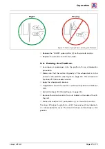
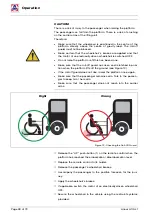
Page 28: ...rd has risen and is latched in posi tion when the platform lifts off the ground see Figure 12 y If the roll off guard does not rise lower the platform once again y Make sure that the passenger remains calm Talk to the passen ger to keep him her calm y Make sure that the passenger does not reach into the carrier arms Right Wrong Figure 12 Checking the Roll Off Guard Release the UP push button 1 on ...

Page 29: ...e to pre vent the Lift from falling against the door of the vehicle if there is a loss of pressure in the hydraulic system see Section 11 6 page 50 CAUTION There is a risk of crushing when folding the linear lift to the vertical stowed position Fingers and hands can be crushed between the carrier struts and the guardrails and between the carrier struts and the platform Therefore y Never reach into...

Page 30: ...nel can be physically overburdened by the ne cessity to operate the linear lift manually in the emergency mode An emergency situation can arise for the passenger on the platform Therefore y Switch the linear lift OFF at the battery isolation switch 5 before using the emergency mode y Initiate repairs to the linear lift as soon as possible 6 1 Raising in the Emergency Mode Switch the linear lift OF...

Page 31: ...g the operating lever up and down until the platform has been raised the desired position see Figure 15 NOTE It takes approx 15 20 strokes before the platform starts moving Figure 15 Pump Actuator 2 Remove the operating lever from the pump actuator Replace the operating lever to its stowage clips ...

Page 32: ...0 Insert the operating lever into the aperture in front of the emergency lowering valve see Figure 16 Turn the lever a little until it engages in the emergency lowering valve Figure 16 Emergency Lowering Valve 1 Open the emergency lowering valve by turning the lever slowly in an anti clockwise direction see Figure 17 Figure 17 Emergency Lowering Valve 2 The platform lowers ...

Page 33: ...2 When the platform has reached the desired position close the emergency lowering valve by turning the operating lever in a clo ckwise direction Remove the lever from the emergency lowering valve Replace the operating lever to its stowage clips ...

Page 34: ...nance and re pair work y If repair work has been carried out on load bearing parts this must be inspected by a technical expert WARNING Risk of personal injury and material damage through the springs If springs under tension are removed or if gas pressure springs are taken apart the sudden uncontrolled release of spring tension can cause severe injuries or material damage Therefore y Do not remove...

Page 35: ...g plates on the underside of the platform for wear Replace the wearing plates if necessary Listen for any unusual noises and look for signs of juddering when operating the linear lift Initiate repairs if necessary weekly Inspect the contact points of the torsion springs 100 on the shaft of the platform for wear and sufficient lubrication grease Apply grease if necessary yearly Inspect the hydrauli...

Page 36: ...pection of the Hydraulic Hoses The inspection of hydraulic hoses extends to y Seating of the fastenings y Damage y Ageing y Brittleness y Porosity If damage is found have the hydraulic hoses replaced 7 5 Yearly Inspection The yearly inspection by a technical expert is basically a visual in spection and functional test It extends to y The condition of all components and devices y An inspection for ...

Page 37: ...Maintenance and Repair Linear Lift AL1 Page 37 of 72 7 6 Maintenance and Inspection Record Maintenance work carried out Date Signature Remarks work carried out ...

Page 38: ...ueries regarding de commissioning and conservation contact our customer services department see Chapter 15 page 70 9 Disposal When the linear lift s useful life has expired it must only be disposed of by qualified specialists The manufacturer will accept no liability for damage caused by incorrect disposal ...

Page 39: ...s the UP push button 1 to switch the remote control ON once again The remote control is defective Check the remote control and it s connections Replace the remote control if necessary The lowering valve is defective Replace the lowering valve The starter switch is defective Check the starter switch and re place if necessary The main fuse has blown Check the main fuse Replace the main fuse if neces...

Page 40: ...est cleanly on the ground when the platform has be en lowered The tilt of the platform is not ad justed correctly Finely adjust the roll off guard see Section 11 1 page 42 The transfer plate does not fold down to the floor an chorage The transfer plate cable linkage is not adjusted correctly Finely adjust the cable linkage see Section 11 2 page 43 The transfer plate makes premature contact with th...

Page 41: ...ft AL1 Page 41 of 72 Fault possible Cause Remedial Measures The linear lift rattles when driving The micro switch on the opposite side to the hydraulic aggregate re quires adjustment Finely adjust the micro switch see Section 11 7 page 51 ...

Page 42: ...hnical training and experience 11 1 Roll Off Guard NOTE On a linear lift with split platform the platform segments must be re adjusted after the roll off guard has been adjusted see Section 11 3 page 44 Park the vehicle on a level surface Fully lower the platform When the platform has been fully lowered the roll off guard must fold down to the ground The edge of the roll off guard must be in conta...

Page 43: ...form once again Check the gap between the edge of the roll off guard and the ground Repeat the adjustment procedure until the platform has the cor rect angle of tilt and the roll off guard rests cleanly on the ground 11 2 Transfer Plate Movement of the transfer plate is controlled by a cable linkage If the cable linkage is too loosely adjusted the transfer plate makes pre mature contact with the f...

Page 44: ...n raise it to the embarkation disembarkation level again see Figure 2 page 14 Repeat the adjustment procedure if necessary 11 3 Split Platform Adjusting the Platform Segments The segments of a split platform must be adjusted such that they in terlock The swivel joints must not be loaded when the platform in the fully lowered position the platform segments must be comple tely in contact with the gr...

Page 45: ...lts in an anti clockwise direction to raise the plat form segments Tighten the locking nuts once again Hold the hexagonal section of the bolt firmly when doing so 11 4 Elbow Joints When the platform has been fully run to the vertical stowed position the side stoppers must rest snugly against the lifting unit see Figure 22 page 46 If this is not the case the platform will rattle when driving Lockin...

Page 46: ...at the battery isolation switch 5 The exact position of the platform in the vertical stowed position is regulated by the length of the connecting tubes see Figure 23 pa ge 47 Loosen the locking nuts on the top and bottom connection eyes of the connecting tubes see Figure 23 page 47 and Figure 24 page 47 NOTE The bottom connection eye locking nuts have left hand threads and the top connecting eye l...

Page 47: ...n order to give the platform a tighter fit when in the vertical stowed position Turn both connecting tubes an equal number of times Tighten the locking nuts once again Run the platform to the vertical stowed position Check that the stoppers rest snugly against the lifting unit see Figure 22 page 46 Repeat the adjustment procedure if necessary Connecting tube Connection eye ...

Page 48: ...t must also be adjusted see Figure 25 Figure 25 Panorama Platform Stowed Position Run the linear lift out completely until the platform rests on the ground and the platform segments are completely extended Loosen the locking nuts on the cable linkages on both sides see Figure 26 Figure 26 Loosening the Locking Nut The length of the cable linkages determines the length of the plat form in the stowe...

Page 49: ... the cable linkages Turn the screws in an anti clockwise direction to lengthen the cable linkages When the platform is in the stowed position the chocks between the two segments of the platform must interlock see Figure 28 The platform segments must be exactly parallel to one another see Figure 29 page 50 Figure 27 Adjusting the Cable Linkages Figure 28 Chocks Adjuster screw Chocks ...

Page 50: ... In order to prevent this from happening arrester hooks are fitted to both sides of the linear lift These engage when the platform tilts in the direction of the rear door Deploy the platform Check the arrester hook connection points for freedom of mo vement see Figure 30 Figure 30 Arrester Hooks If there is no freedom of movement slacken the connection points a little Clean the connection points i...

Page 51: ...ks engage 11 7 Micro Switches A total of three micro switches are installed in the carrier arms of the linear lift They are actuated by the abrasion protectors on the elbow joints see Figure 31 and Figure 32 Figure 31 Micro Switches Figure 32 Aggregate Side Micro Switches The opposite side to the aggregate Micro switch 2 Micro switch 1 Micro switch 3 The same side the aggregate Micro switch 2 Abra...

Page 52: ... 1 and FOLD 4 push buttons see Section 5 6 page 27 Press and hold the UNFOLD push button 3 on the remote control The platform lowers to the vertical position at the embarkation disembarkation level Whilst the platform is being lowered the abrasion protectors on the elbow joints slide along the carrier arms The micro switches are actuated by the abrasion protector When the abrasion protector has sl...

Page 53: ... micro switches in the direction of the hydraulic aggre gate When doing so make sure that the micro switches protrude suf ficiently from the carrier arm If not the abrasion protector will not actuate them Tighten the micro switch fastening screws once again Run the platform to the vertical stowed position again Lower the platform again by pressing the UNFOLD push button 3 until the platform stops ...

Page 54: ...ent procedure Adjusting the micro switch on the side opposite the aggre gate Run the platform to the embarkation disembarkation level by pressing the UNFOLD 3 or UP 1 push button Press and hold the FOLD push button 4 Release the FOLD push button 4 as soon as the platform has stopped If the platform does not reach the vertical stowed position but stops shortly after the FOLD push button 4 was press...

Page 55: ...Fine Adjustments Linear Lift AL1 Page 55 of 72 Carry out the above checks once again If necessary re adjust the micro switch ...

Page 56: ...st see Sec tion 12 2 page 58 A technical expert is someone who by virtue of their technical trai ning and experience has sufficient knowledge in the field of lifting platforms and is sufficiently familiar with the relevant national occu pational health and safety regulations accident prevention regulati ons and recognised rules of sound engineering practice e g BG rules DIN standards VDE provision...

Page 57: ...Inspection Log Linear Lift AL1 Page 57 of 72 12 1 Inspection Log Master Data Sheet linear lift Master Data Sheet Serial No Type Number plate Owner Year built Commissioned on see rating plate ...

Page 58: ...sual inspection of the condition of the entire linear lift Hydraulic system Power aggregate Functional check of the valves Hydraulic hoses Inspect all hydraulic hoses and the burst pipe protec tion for leaks Connections in accordance with the wiring diagram Hydraulic cylinders Check for leaks and functionality Electrical System Push buttons on the remote control Functional check Battery isolation ...

Page 59: ... the inspection prior to commissioning To be observed if installed by a third party company Installation inspection for Serial No Type Number plate Installation has been carried out correctly Place date Installation company Company stamp Technical expert Signature see rating plate ...

Page 60: ...the inspection list a re inspection No the following defects were found There are no issues to preclude continued operation Re inspection is required Place date Company Company stamp Signature technical expert Note has been taken of the result of the inspection All deficiencies have been rectified Confirmation by the owner or his representative with date and signature Place date Signature owner se...

Page 61: ...the inspection list a re inspection No the following defects were found There are no issues to preclude continued operation Re inspection is required Place date Company Company stamp Signature technical expert Note has been taken of the result of the inspection All deficiencies have been rectified Confirmation by the owner or his representative with date and signature Place date Signature owner se...

Page 62: ...the inspection list a re inspection No the following defects were found There are no issues to preclude continued operation Re inspection is required Place date Company Company stamp Signature technical expert Note has been taken of the result of the inspection All deficiencies have been rectified Confirmation by the owner or his representative with date and signature Place date Signature owner se...

Page 63: ...the inspection list a re inspection No the following defects were found There are no issues to preclude continued operation Re inspection is required Place date Company Company stamp Signature technical expert Note has been taken of the result of the inspection All deficiencies have been rectified Confirmation by the owner or his representative with date and signature Place date Signature owner se...

Page 64: ...the inspection list a re inspection No the following defects were found There are no issues to preclude continued operation Re inspection is required Place date Company Company stamp Signature technical expert Note has been taken of the result of the inspection All deficiencies have been rectified Confirmation by the owner or his representative with date and signature Place date Signature owner se...

Page 65: ...the inspection list a re inspection No the following defects were found There are no issues to preclude continued operation Re inspection is required Place date Company Company stamp Signature technical expert Note has been taken of the result of the inspection All deficiencies have been rectified Confirmation by the owner or his representative with date and signature Place date Signature owner se...

Page 66: ...the inspection list a re inspection No the following defects were found There are no issues to preclude continued operation Re inspection is required Place date Company Company stamp Signature technical expert Note has been taken of the result of the inspection All deficiencies have been rectified Confirmation by the owner or his representative with date and signature Place date Signature owner se...

Page 67: ...lectrical Circuit Diagrams Figure 34 Electrical Circuit Diagram 1 Position indicator Blinker lamp Position indicator Blinker lamp Blinker relay 12V Micro switch Fuse 7 5 A DC motor12V Battery isolation switch Vehicle Fuse 110 A Starter battery 12 V Starter switch ...

Page 68: ...cc to IEC 60757 Black BK Blue BU Brown BN Grey GY Red RD White WH Orange OG Dark Blue DBU Yellow YE Red White RDWH Green GN Blue White BUWH Micro switch Pressure switch Control module Manual push buttons Micro switch Micro switch Changeover relay Changeover relay Magnetic valve Magnetic valve 1 5 l min Changeover relay Starter switch Starter switch 87a 87 ...

Page 69: ...iagram Linear Lift AL1 Page 69 of 72 14 Hydraulic Circuit Diagram Figure 36 Hydraulic Circuit Diagram Block material Aluminium bright p DBV 92 bar 2 bar p max 210 bar Valve voltage U 12 V DC Installation position vertical ...

Page 70: ... 0 44 89 62 45 service hubmatik amf bruns de www amf bruns de Further service information and a spare parts catalogue can be found in the service section of our Internet site NOTE Guarantee work on the linear lift must only be carried out with the prior agreement of AMF Bruns GmbH Co KG The costs of such work will not be accepted by AMF Bruns without prior agreement In case of a claim AMF Bruns Gm...

Page 71: ...null and void if unauthorised modifications are made to the machine Designation linear lift Type AL1 Solid AL1 Panorama AL1 Split Manufacturer Company AMF Bruns GmbH Co KG Address Hauptstraße 101 26689 Apen Harmonised standards applied DIN EN 1756 2 DIN EN ISO 12100 Other technical standards and specifications applied DIN 32983 DIN 75078 1 BGR 500 Authorised representative for the technical docume...

Page 72: ...Art No 10018347 07 2021 AMF Bruns GmbH Co KG Hauptstraße 101 D 26689 Apen Telephone 49 0 44 89 72 72 22 Fax 49 0 44 89 62 45 service hubmatik amf bruns de www amf bruns de ...

Reviews: