background image


AMF 90XL

i

 PINSPOTTER 


400-088-011 

Page 4-6 

Rev. 10/04 

4.6 

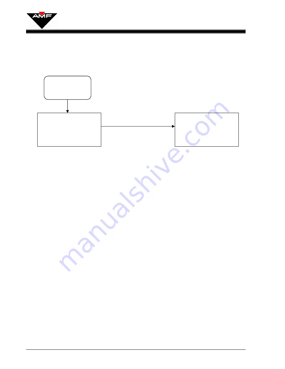
PROBLEM:  Ball wobbles on track rail assembly. 


START 

Ball lift assembly 

not centered 

between track 

rails? 

Center ball lift 

assembly at both 

top and bottom of 

track rail


assembly.

YES

Summary of Contents for 90XLi

Page 1: ...PBL ASSEMBLED REVISED POSITIVE BALL LIFT PBL AMF 90XLi Pinspotter Manual Supplement 400 088 011 Rev A ...

Page 2: ......

Page 3: ...ntain typographical errors inaccuracies or errors of omission AMF Bowling Products Inc cannot be held responsible for any claims resulting from these errors 4 DOCUMENT UPDATES AMF Bowling Products Inc reserves the right to revise and or update this manual at any time without obligation to notify any person or entity of such revision The document number revision level and date below indicate the ed...

Page 4: ......

Page 5: ...AMF Positive Ball Lift PBL Manual Rev A 400 088 011 SUMMARY OF CHANGES Change No ECR No List of Effective Pages Page Change No Effective Date All Original 10 29 2004 ...

Page 6: ......

Page 7: ... 7 2 10 Checking the Reset Cams 2 8 2 11 Positive Ball Lift Assembly Adjustment 2 9 2 12 Lift Arm Adjustment 2 10 2 13 Rubber Bumper Adjustment 2 11 3 0 LUBRICATION INSTRUCTIONS 3 1 3 1 Lubrication 3 1 3 2 Lubricant Symbols 3 1 3 3 Lubrication Points 3 2 3 3 1 Positive Ball Lift 3 2 3 3 2 Positive Ball Lift 3 3 3 3 3 Belt Tensioner 3 4 3 3 4 Light Ball Sensor 3 5 3 3 5 Ratchet Wheel 3 5 4 0 TROUBL...

Page 8: ...o clear pin jams 4 9 5 0 DRAWINGS PARTS LISTS 5 1 Positive Ball Lift assembled 5 2 Positive Ball Lift exploded view 5 4 Positive Ball Lift exploded view continued 5 6 PBL Belt Tensioner Assembly 5 8 PBL Belt Tightener Assembly 5 10 PBL Ratchet Drive Assembly 5 12 PBL Light Ball Sensor Assembly 5 14 PBL Light Ball Sensor Assembly continued 5 16 PBL Track Rail Assembly 5 18 ...

Page 9: ... unauthorized personnel should be allowed in the pit area Keep in mind that the pinspotter performs a series of mechanical motions and electrical actions during each cycle and that bodily injury could result should personnel enter the machine when power is on When working in a pinspotter it is recommended that power also be turned off on adjacent machines The belts and pulleys of the Positive Ball...

Page 10: ... unsafe for you as well as for others who follow in your place indicates a hazardous situation that presents a potentially crippling or life threatening situation indicates a potentially hazardous situation that could result in serious injury or equipment damage indicates a potentially hazardous situation that could result in minor to moderate injury if not avoided It may also be used to alert aga...

Page 11: ...lts It is also important to understand that the use of these symbols and labels is not all inclusive because it is impossible to warn of all the possible hazards and consequences that could result from failure to follow these instructions Trained and competent bowling center mechanics are able to recognize and avoid potentially hazardous situations ...

Page 12: ...enance 3 Once maintenance is complete replace all guards 4 Reconnect the power plug The Positive Ball Lift has two guards see Figure 1 designed specifically to limit access to the ball lift s moving parts These guards must remain in place during pinspotter operation The Upper Ball Lift Upper Guard item 1 limits access to the main lift belt and upper wheel and to bowling balls exiting the lift The ...

Page 13: ...ty Introduction Operation Adjustments Lubrication Troubleshooting and Drawings and Parts Lists The Safety section provides information on precautions that should be taken when working in and around the Positive Ball Lift including examples of safety labels and symbols used on the pinspotter to indicate potential hazards The Introduction Section outlines the manual The Operation and Adjustment Sect...

Page 14: ...AMF 90XLi PINSPOTTER 400 088 011 Page 1 2 Rev 10 04 This Page Intentionally Left Blank ...

Page 15: ...tment 400 088 011 Page 2 1 Rev Date 10 04 2 0 POSITIVE BALL LIFT OPERATION ADJUSTMENT Figure 2 1 Ball Lift Assembly Track Rail Assembly Belt Tensioner Belt Tightener Ratchet Drive Assembly Light Ball Sensor PBL ASSEMBLED REVISED ...

Page 16: ...o belt tightener springs and the ratchet drive belt tensioner spring from between the pinspotters 4 Remove the carpet drive belts the ratchet drive belt and the upper paddle drive belt from the PBL pulleys 5 Remove the clamp studs from the upper and lower ball lift shaft mounting brackets and lift the ball lift assembly out of pinspotter 2 3 Positive Ball Lift Installation 1 Place the upper ball l...

Page 17: ...port shaft plates 8 If an offset adjustment was made or if a different ball lift is being installed verify correct bumper height adjustment in accordance with Section 2 13 9 Install all drive belts springs and spring extensions 10 Reinstall the upper and rear guards 11 Test the ball lift by running several balls through it to verify smooth operation that the belt does not slip and that the unit re...

Page 18: ...er roller Figure 2 4 2 6 Sensor Adjustment 1 If the height of the cam follower must be adjusted a Remove the light ball sensor from the machine b Disconnect the support plate tension spring c Add or remove washers as needed between the cam follower and the support plate d Reconnect the support plate tension spring e Reinstall the light ball sensor in the pinspotter 2 The ball lift sensor support a...

Page 19: ... the full clockwise position then tighten the pivot crank nut to prevent the adjusting plate from moving 5 Move the rudder arm back and forth so that it touches the rubber bumper on each side plate The arm should move freely with no interference If the paddle is not centered in the door opening it may be necessary to adjust the length of the rudder arm for front to back alignment and or shim the r...

Page 20: ...wards the even machine The rod assembly has right hand threads on both ends so the rod end must be removed from the crank pin to make adjustments 9 Loosen the pivot crank nut on the crank plate and rotate the plate in a counterclockwise manner to increase the overall stroke of the rudder arm The correct adjustment is achieved when the rudder arm touches each rubber bumper on the left and right sid...

Page 21: ...ure 2 8 3 To adjust loosen the trip cam bolts reposition the cam and retighten the bolts 4 Recheck the clearance after tightening 2 9 Reset Cam Adjustment 1 Rotate the drive pulley to place the rudder arm as far left as it will go striking the bumper Hold this position 2 Install the left reset cam and move its angled surface to touch the trip cam follower Tighten the cam s mounting bolt 3 Repeat S...

Page 22: ...osition adjust the reset cam inward a small amount and repeat Steps 1 and 2 4 Check and as necessary adjust the other trip cam follower roller in the same manner 5 Install the belt on the rudder drive pulley 6 Replace the spring on the belt tensioner 7 On the chassis turn the Back End switch ON Keep your hands away from belts pulleys and other rotating equipment Failure to do so can result in seve...

Page 23: ... upper and lower mounting brackets adjust the lift from side to side as needed and retighten the nuts Figure 2 9 2 The Positive Ball Lift belt tension spring should be compressed to 4 1 8 1 8 for proper tension on the lift belt see Figure 2 10 Take this measurement between the top edge of the spring and the upper edge of the lower spring retainer Adjust by tightening or loosening the upper retaini...

Page 24: ...e rod that connects between the lift arm and the ratchet drive assembly see Figure 2 12 The rod has right hand threads on both ends so one end of the rod must be disconnected in order to make the adjustment Shortening the rod raises the lift arm lengthening the rod lowers the lift arm Tighten the jam nuts after completing the adjustment Figure 2 11 Figure 2 12 Ratchet Drive Assembly LIFT ARM ADJUS...

Page 25: ...l and the ball lift belt This clearance should be between 3 8 and 1 2 inch The increase in clearance from earlier units is needed because of the thicker rail covers of the new Gripper ball return Figure 2 13 3 Adjust this clearance by adjusting the height of the rubber bumpers see Figure 2 14 Following adjustment tighten the jam nuts Figure 2 14 PBL CLEARANCE 3 8 to 1 2 clearance Rubber Bumper Jam...

Page 26: ...AMF 90XLi PINSPOTTER 400 088 011 Page 2 12 Rev 10 04 This Page Intentionally Left Blank ...

Page 27: ...ler Before lubrication of exposed parts or surfaces it is important that the old lubricant first be removed It is also very important to clean the ball lift as you lubricate This section of the manual shows the points of lubrication the correct lubricants to use and the frequency of lubrication for each part of the ball lift 3 2 LUBRICANT SYMBOLS OILING Items indicated by a number within a square ...

Page 28: ...2 Paddle drive pulley shaft 2 places apply 2 drops of oil every 3 months 3 Pin wheel belt tensioner 2 places apply 2 drops of oil every 3 months 4 PBL lift arm flange bearing 2 places apply 2 drops of oil every 3 months 5 Carpet belt tensioner assembly 6 places apply 2 drops of oil every 2 months 1 Apply grease with Grease Gun every 6 months 3 1 2 5 1 4 Figure 4 1 PBL ASSEMBLED REVISED ...

Page 29: ...oil to each side every 3 months 2 Lower yoke pivot points 4 places apply 2 drops of oil every 3 months 3 Upper yoke pivot points 4 places apply 2 drops of oil every 3 months 4 Upper yoke upper shaft 2 places apply 2 drops of oil every 3 months 5 Lower yoke upper shaft 2 places apply 2 drops of oil every 3 months Figure 3 2 PBL 1 5 4 2 3 ...

Page 30: ...SIONER Figure 3 3 1 Pulley 2 places apply 1 drop of oil to each side every 3 months 2 Hanger arm center pivot points 6 places apply 1 drop of oil every 3 months 3 Lower shaft sleeve bearings 4 places apply 1 drop of oil every 3 months BELT TENSIONER 1 3 2 2 Figure 3 3 ...

Page 31: ...nd rudder cam assembly outlined within the square below Friction is required in this area to allow the sensor to operate properly Figure 3 4 3 3 5 RATCHET WHEEL Figure 3 5 1 Ratchet wheel shaft flange bearings 2 places apply 2 drops of oil every 3 months RATCHET WHEEL 1 Figure 3 5 DO NOT LUBRICATE ANY COMPONENTS WITHIN THIS BOX SENSOR FRONT VIEW ...

Page 32: ...AMF 90XLi PINSPOTTER 400 088 011 Page 3 6 Rev 10 04 This Page Intentionally Left Blank ...

Page 33: ...ampener Repair or replace as needed START Ball lift too low Lift arm assembly not centered between side plates Rudder jammed Interference caused by bounce plate Bounce plate support bracket loose or broken Adjust bumper Adjust lift arm Adjust rudder Repair or replace NO NO NO NO YES YES YES YES YES Light Ball Sensor out of adjustment Adjust per Section 2 of manual NO YES ...

Page 34: ...START V belt tightener spring broken or stretched V belt is slipping on pulleys V belt stretched or worn Ball lift belt tension low Belt tension spring retainer nut loose Setscrew loose on drive pulley Pulley rotates but ball lift does not Ball lift clutch broken or worn Replace clutch Tighten setscrew Replace V belt Replace spring NO NO NO NO YES YES YES YES ...

Page 35: ...s Replace crank assembly YES START Ball lift assembly position too high Lift arm sticks in raised position Ball spins on lower track cover section Ball bounces on lift arm Lift arm does not engage ratchet clutch Adjust height of rubber stops as required to obtain proper ball lift height Replace polyurethane tube NO NO NO NO YES YES YES Oil and dirt buildup Clean track rail and PBL belt NO YES ...

Page 36: ...r slides back to the lift arm Lower track cover worn Replace lower track cover NO YES NO Ball lift belt too loose Adjust lift spring tension YES Lift belt is dirty or oily Clean ball lift belt START YES Ball lift too far to rear Adjust lift at both adjustable shafts to move lift forward NO YES Adjust upper tension bracket ...

Page 37: ...ent shock travel Lift belt to track rail clearance is less than 4 5 inches Sticking shock absorber Ball lift not centered Center lift Replace shock assembly Reset ball lift height Change shock mount position or shock assembly NO NO NO YES YES YES YES Track rail and down sweep not centered between machines Center unit at top of ball lift NO YES ...

Page 38: ...TTER 400 088 011 Page 4 6 Rev 10 04 4 6 PROBLEM Ball wobbles on track rail assembly START Ball lift assembly not centered between track rails Center ball lift assembly at both top and bottom of track rail assembly YES ...

Page 39: ...ll lift belt leaves V groove of sheaves START Ball lift assembly not centered between track rails Center ball lift assembly at both top and bottom of track rail assembly Insufficient belt tension Adjust length of ball lift spring NO YES YES Ball lift belt worn Replace Belt NO YES ...

Page 40: ...il to reset to proper height Sensor oily or dirty and needs adjusting Ball lift assembly too low Trip cam followers fail to hold position when actuated Rudder cams fail to clear top of 1 inch diameter follower Reset rudder cams Remove washers from under 1 inch diameter cam follower Adjust height of rubber stops as required to obtain proper ball lift height Disassemble clean and replace do not lubr...

Page 41: ...s fail to engage 1 inch diameter follower Excessive rudder cam to top of cam follower clearance Sensor assembly is oily Sensor spring is too weak Reset trip cam Replace sensor spring Add washers under 1 inch diameter cam follower Remove sensor assembly disassemble clean and replace Do not lubricate NO NO NO YES YES YES YES ...

Page 42: ...AMF 90XLi PINSPOTTER 400 088 011 Page 4 10 Rev 10 04 This Page Intentionally Left Blank ...

Page 43: ...SECTION 5 0 400 088 011 Rev 10 04 Page 5 1 D DR RA AW WI IN NG GS S P PA AR RT TS S L LI IS ST TS S ...

Page 44: ...SECTION 5 0 Drawings Parts Lists 400 088 011 Page 5 2 Rev Date 10 04 POSITIVE BALL LIFT PBL ASSEMBLED POSITIVE BALL LIFT ASSEMBLED REVISED ...

Page 45: ...ENSION ROD 8 2 000 021 814 WIPER CLOTH RING 9 1 000 029 629 DOWN SWEEP WELDMENT 10 1 070 004 670 DUST TRAP 11 4 070 004 654 TRACK SUPPORT BRACKET 12 8 809 865 285 SCREW HEX 3 8 16 X 1 3 4 13 74 948 767 132 WASHER 13 32 X 13 16 X 1 16 14 20 844 065 002 NUT STOVER LOCK 3 8 16 15 1 088 001 235 TRACK RAIL ASSEMBLY 16 4 070 008 212 SPACER 17 1 070 008 207 RAIL WELDMENT 18 1 070 011 148 V BELT PADDLE DR...

Page 46: ...SECTION 5 0 Drawings Parts Lists 400 088 011 Page 5 4 Rev Date 10 04 POSITIVE BALL LIFT PBL EXPLODED VIEW ...

Page 47: ...LINK 31 1 070 008 218 SPACER LONG 9A 1 000 024 720 LINK ASSY UPPER includes 6 9 10 51 32 1 000 029 660 SHAFT 9A1 1 000 024 651 LINK ASSY LOWER includes 9 10 37 33 2 919 005 600 RETAINING RING 10 4 900 110 121 SLEEVE BEARING 628 X 3 4 34 2 948 983 212 WASHER FLAT 1 5 16 X 21 32 X 093 11 4 807 265 060 SETSCREW 3 8 16 X 3 8 35 1 839 549 002 NUT FLEX LOCK 20 12 1 000 024 606 UPPER SUPPORT 36 2 900 212...

Page 48: ...SECTION 5 0 Drawings Parts Lists 400 088 011 Page 5 6 Rev Date 10 04 POSITIVE BALL LIFT PBL EXPLODED VIEW continued ...

Page 49: ...AINER 48 1 000 024 605 LOWER RETAINER 49 1 808 849 565 SCREW FLAT HEAD 20 X 3 1 2 50 1 070 007 192 WASHER 51 1 000 024 716 SPRING HOLDER 52 2 000 027 996 RUBBER CUSHION 53 1 831 566 002 NUT HEX 3 8 24 54 2 000 027 998 RETAINER 55 2 000 028 057 RETAINER 56 2 070 008 212 SPACER 57 1 070 008 211 SHEAVE 58 1 000 024 811 PULLEY ASSEMBLY R H 59 1 839 665 002 NUT FLEX LOCK 3 8 16 60 1 000 024 659 LOWER Y...

Page 50: ...SECTION 5 0 Drawings Parts Lists 400 088 011 Page 5 8 Rev Date 10 04 PBL BELT TENSIONER ASSEMBLY ...

Page 51: ... 2 000 029 659 HANGER ARM ASSY includes items 2 3 4 4 919 005 600 RETAINING RING 5 1 000 029 606 PIVOT SHAFT SHORT 6 1 070 011 147 V BELT PADDLE DRIVE LOWER 7 1 919 005 500 RETAINING RING 8 2 900 208 120 BEARING 9 1 070 011 131 PULLEY WELDMENT 10 1 000 027 264 SPACER 11 1 090 002 016 SPRING EXTENSION 12 1 090 002 014 SHAFT 13 1 919 005 900 RETAINING RING 14 1 000 026 031 SPRING PBL BELT TENSIONER ...

Page 52: ...SECTION 5 0 Drawings Parts Lists 400 088 011 Page 5 10 Rev Date 10 04 PBL BELT TIGHTENER ASSEMBLY ...

Page 53: ...M ASSY R H MACHINE includes 2 3 2A1 1 070 011 523 BELT TIGHTENER R H MACHINE includes 2 3 4 5 6 7 8 10 3 4 900 112 121 SLEEVE BEARING 753 X 75 4 2 701 316 041 THRUST BEARING 51 X 1 X 1 16 5 4 900 208 161 FLANGED BEARING 503 X 875 6 2 see 6A IDLER PULLEY 6A 2 000 021 408 IDLER PULLEY ASSY includes 5 6 7 4 948 975 172 WASHER FLAT 1 1 16 X 17 32 X 3 32 8 4 963 600 002 X WASHER 1 4 9 2 919 005 800 RET...

Page 54: ...SECTION 5 0 Drawings Parts Lists 400 088 011 Page 5 12 Rev Date 10 04 PBL RATCHET DRIVE ASSEMBLY ...

Page 55: ... 549 002 NUT FLEX LOCK 20 8 1 070 011 033 PULLEY 9 32 000 026 865 WASHER 10 16 070 011 030 ROLLER 11 16 070 011 031 ROLLER SPACER 12 16 809 849 205 SCREW HEX 20 X 1 13 2 919 000 600 RETAINING RING 14 2 000 024 679 BALL BEARING 625 X 1 375 15 1 070 011 013 CRANK WELDMENT 15A 1 070 011 037 CRANK ASSY includes 13 14 15 16 16 1 070 006 142 BUMPER 17 3 919 005 200 RETAINING RING 18 3 070 011 040 RATCHE...

Page 56: ...SECTION 5 0 Drawings Parts Lists 400 088 011 Page 5 14 Rev Date 10 04 PBL LIGHT BALL SENSOR ASSEMBLY ...

Page 57: ...0 208 091 FLANGED BEARING 503 X 690 X 9 16 13 1 838 866 002 NUT HEX LOCK 3 8 24 34 2 722 985 512 COMPRESSION SPRING 14 2 070 011 096 ROLLER 35 2 900 205 081 FLANGED BEARING 315 X 44 X 1 2 14A 2 070 011 105 ROLLER ASSEMBLY includes 14 35 36 1 809 857 880 SCREW HEX 5 16 18 X 5 1 2 15 2 070 011 077 TRIP FINGER 37 2 090 007 276 BRACKET 16 2 722 971 522 COMPRESSION SPRING 38 1 070 011 040 RATCHET ROLLE...

Page 58: ...SECTION 5 0 Drawings Parts Lists 400 088 011 Page 5 16 Rev Date 10 04 PBL LIGHT BALL SENSOR ASSEMBLY continued ...

Page 59: ...405 SCREW HEX 3 8 16 X 2 52 1 070 011 121 PLUG 53 2 948 767 132 WASHER FLAT 13 16 X 13 32 X 1 16 54 1 844 065 002 NUT FLEX LOCK 3 8 16 55 1 070 011 122 RUDDER ARM 56 1 907 000 900 KEY 57 1 831 573 002 NUT HEX 1 2 13 58 1 000 024 616 CLAMP STUD 59 4 900 212 201 FLANGED BEARING 753 X 1 X 1 25 60 1 000 024 615 SHAFT 61 1 070 011 079 RUDDER DRIVE WELDMENT 61A 1 070 011 080 RUDDER DRIVE ASSY incl 33 59...

Page 60: ...SECTION 5 0 Drawings Parts Lists 400 088 011 Page 5 18 Rev Date 10 04 PBL TRACK RAIL ASSEMBLY PBL TRACK RAIL ASSEMBLY REVISED ITEM 12 14A1 ...

Page 61: ...OCK 5 16 18 12 0 22 948 767 132 WASHER FLAT 13 32 X 13 16 X 1 16 13 2 900 210 161 FLANGED BEARING 628 x 1 14 1 070 011 411 LIFT ARM WELDMENT 14A 1 070 011 412 LIFT ARM ASSEMBLY includes 13 14 14A1 1 070 011 413 LIFT ASSEMBLY incl 9 10 14A 15 20 22 15 4 090 002 024 CRADLE LINER 16 1 838 866 002 NUT HEX 3 8 24 17 1 090 005 259 ROD ASSEMBLY 18 1 070 011 218 LEVER ARM WELDMENT 19 2 808 857 280 SCREW F...

Page 62: ......

Reviews: