AMG Systems Ltd. reserves the right to make changes to this document without
notice. The information herein is believed to be accurate. No responsibility is
assumed by AMG for its use.
Page 1 of 9
AMG2783A-1-DR-
CWDMn,m -SF Instruction
Sheet D15185-00
AMG2783A-1-DR-CWDMnm-SF
Instruction Manual
Single Channel Video Insert Unit with Bi-directional Data
Dual Redundant on a single fibre ring
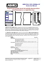
AMG2783A-1-DR-CWDMnm-SF
is a single channel video insert unit designed to transmit a video
signal on to a single dual redundant optical fibre ring. It also provides a RS485/RS422 bi-directional
data channel. It is designed to plug into non-standard rackmount housing where power is supplied to
the rear of the unit to two power supply sockets. Up to 32 units can be attached to the same single
fibre optic ring to transmit up to 32 real time high quality video signals.
The
AMG2783A-1-DR-CWDMnm-SF
is designed to operate with the
AMG2784-DR-CWDMnm-SF
eight channel video and data receiver. Each receiver will ‘drop off’ up to eight video channels which
are being transmitted around the single fibre ring on the corresponding CWDM wavelengths. Up to 4
receivers operating in different wavelength bands give a capacity of up to 32 video signals on the
same single fibre ring.
Index
Page No.
Introduction .......................................................................................................... 2
Unit Functional Schematic................................................................. 2
Optical System Connection ............................................................... 2
Dual Redundant Operation................................................................ 2
Calculation of maximum transmission distances between nodes ..... 3
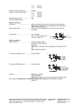
Connections ......................................................................................................... 6
Video Input connection...................................................................... 6
Optical Connections .......................................................................... 6
Power Connections ........................................................................... 6
Data Connections.............................................................................. 7
Indicators
........................................................................................................... 7
Physical Information ........................................................................................... 7
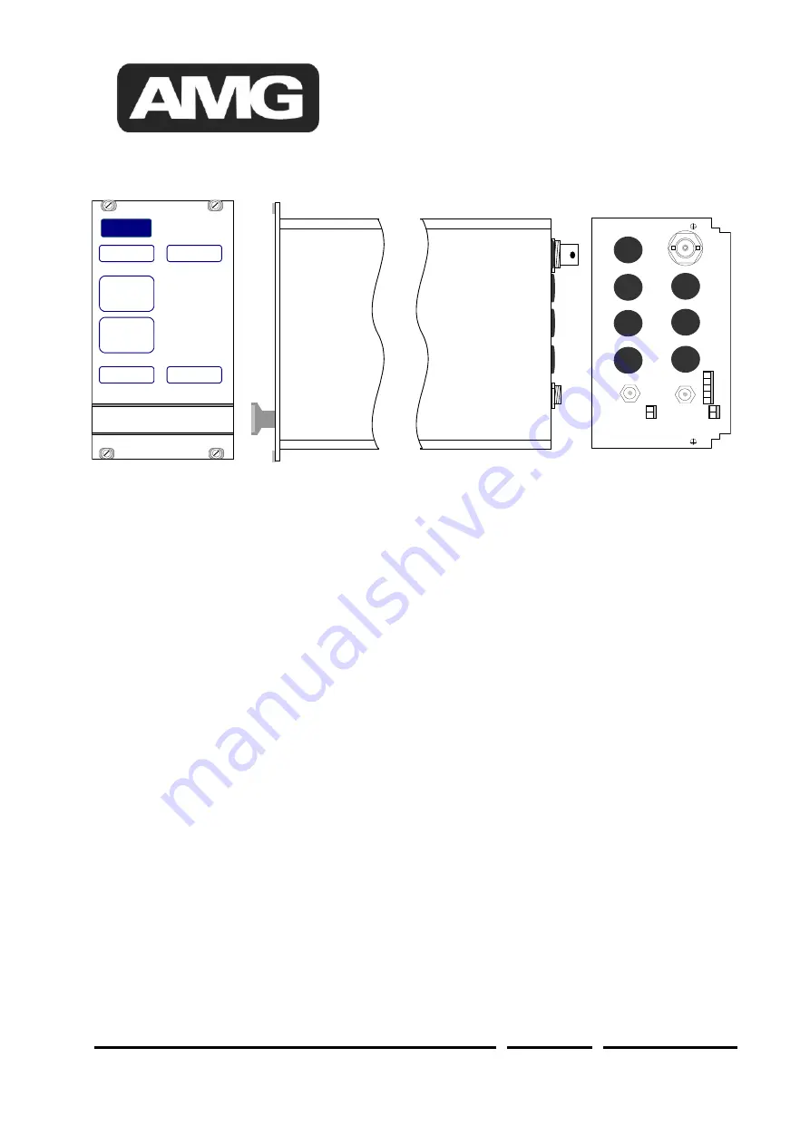
Dimensions........................................................................................ 7
Mounting Details................................................................................ 8
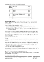
Configuration of the RS422/RS485 Data Channel ............................................ 8
Video Input Channel Configuration ................................................................... 8
SW1 Switch Settings ........................................................................................... 9
Removal from the Case ....................................................................................... 9
Safety
........................................................................................................... 10
V
I
D
E
O
OPTO IN
D
A
T
A
CH 5
CH 6
CH 7
CH 8
CH 4
CH 3
CH 2
CH 1
OPTO OUT
2783A-1-DR-CWDM1/2-SF
AMG
PRIMARY OPTO SYNC
TX
O O
RX
SECONDARY OPTO SYNC
TX
O O
RX
VIDEO PRESENT
CH1
O
O
RX
CH1
O O
RX
DATA PRESENT
-------------------------
1 CH VIDEO INSERT
+
DATA TX/RX
POWER
O
POWER
O

