AMG Systems Ltd. reserves the right to make changes to this document without
notice. The information herein is believed to be accurate. No responsibility is
assumed by AMG for its use.
Page 1 of 8
AMG2783R-1-DR-SF
Instruction Sheet D15680-
00
AMG2783R-1-DR-SF
Instruction Manual
Single Channel Video Insert Unit with Bi-directional Data
Dual Redundant on a single fibre ring
The
AMG2783R-1-DR-SF
is a single channel video insert unit designed to transmit a video signal on
to a single dual redundant optical fibre ring. It also provides a RS485/RS422 bi-directional data
channel. It is designed to be mounted in an
AMG2005
19” rackmount subrack.
The
AMG2783R-1-DR-SF
is designed to operate with the
AMG2784RN-DR-SF
eight channel video
and data receiver. Each receiver will ‘drop off’ up to eight video channels that are being transmitted
around the single fibre ring.
Index
Page No.
Introduction .......................................................................................................... 2
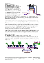
Unit Functional Schematic................................................................. 2
Optical System Connection ............................................................... 2
Dual Redundant Operation................................................................ 3
Connections ......................................................................................................... 4
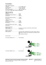
Video Input connection...................................................................... 4
Optical Connections .......................................................................... 4
Power Connections ........................................................................... 4
Data Connections.............................................................................. 5
Indicators
........................................................................................................... 6
Physical Information ........................................................................................... 6
Dimensions........................................................................................ 6
Mounting Details................................................................................ 6
Configuration of the RS422/RS485 Data Channel ............................................ 7
Video Input Channel Configuration ................................................................... 7
SW1 Switch Settings ........................................................................................... 8
Removal from the Case ....................................................................................... 9
Safety
........................................................................................................... 9
P
R
IM
A
R
Y
CH 4
CH 3
CH 2
CH 1
CH 8
CH 7
CH 6
CH 5
OPTO
OUT
OPTO
IN
S
E
C
O
N
D
A
R
Y
D
A
T
A
D
A
T
A
2783R-1-DR-SF
AMG
PRIMARY OPTO SYNC
TX O
O
RX
SECONDARY OPTO SYNC
TX O
O
RX
VIDEO PRESENT
CH1 O
CH1 O
O
RX
DATA PRESENT
-------------------------
1 CH VIDEO INSERT
+
DATA TX/RX
POWER
O
POWER
O


