background image

AMG Systems Ltd. reserves the right to make changes to this
document without notice. The information herein is believed to
be accurate. No responsibility is assumed by AMG for its use.

Page 1 of 8

AMG5715 Instruction Sheet D17053-
05.doc

AMG5715

Instruction Manual

Single Channel Video Transmit Unit with one Bi-directional

Data Channel and two Uni-directional Alarms for a

Singlemode Fibre Link

The

AMG5715

is a compact standalone one channel video transmit unit designed to transmit 1 video

signal and transmit and receive 1 data signal plus 2 Uni-directional alarms over one Singlemode
optical fibre.

The

AMG5715

is designed to be powered using an

AMG2001

standalone power supply.

The

AMG5715

is designed to operate with an

AMG5716 / AMG5716R

single channel or

AMG5726 /

AMG5726R

dual channel video receive unit in a point to point configuration. The R suffix in the partno.

indicates a rackmount configuration.

Summary of Contents for AMG5715

Page 1: ...ional Alarms for a Singlemode Fibre Link The AMG5715 is a compact standalone one channel video transmit unit designed to transmit 1 video signal and transmit and receive 1 data signal plus 2 Uni direc...

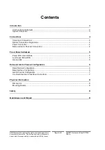
Page 2: ...al Connection 3 Connections 4 Video Input Connections 4 Optical Connections Singlemode 4 Power Connection 4 Data and Alarm Channel Connections 4 Front Panel Indicators 5 Power LED Video Data 5 Low Spe...

Page 3: ...Introduction Unit Functional Schematic The AMG5715 transmits 1 video plus 1 data and 2 uni directional alarm signals to the AMG5716 receive unit It also receives 1 data signal transmitted from the AM...

Page 4: ...Connector SC PC Primary Optical Launch Power 10dBm Transmit Wavelength 1310nm Primary Optical Sensitivity 30dBm Receive Wavelength 1510nm Minimum Optical Dynamic Range 20dB Power Connection Connector...

Page 5: ...n IN IN Off tri state off or no connection on IN IN Data Present IN RS232 Green logic zero V present on input IN Red logic transitions present on input IN Off logic one V present on input IN IN corres...

Page 6: ...the differential voltage level across the input A differential level below 600mV positive or negative will be detected as a tri state condition A level above 600mV positive or negative will be detect...

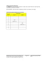
Page 7: ...on Sheet D17053 05 doc Alarm Channel Configuration The AMG5715 provides 2 uni directional alarm contact closure inputs Each alarm input is typically connected to a contact closure switch Each ALARM IN...

Page 8: ...follow good practice when working with optical fibre systems This includes Do not stare with unprotected eyes or with any unapproved collimating device at fibre ends or connector faces or point them...

Reviews: