18
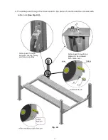
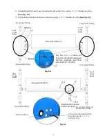
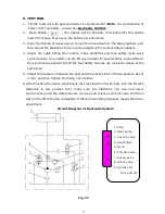
4.Finish oil hose and air line connecting
(See Fig. 28)
.
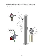
5. Install oil-water separator and manual control air valve.
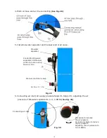
5. Connecting air inlet (Air supply pressure 5kg/cm
2
- 8kg/cm
2
), adjusting the air
pressure of Oil-water separator to 0.4 - 0.6MPa
(See Fig. 30)
.
Fig. 30
Clockwise to increase
the air pressure
Counter-clockwise to reduce
the air pressure
Adjusting the air pressure to
0.4~0.6MPa
Connecting air inlet
Oil-water
separator
Connecting Oil-water
separator and Manual
control air valve using
black air line
Manual control air valve
Air line
¢6×¢
4
72
Fig. 29
Fig. 28
54
Summary of Contents for PRO-14
Page 1: ...FOUR POST LIFT PRO 14...
Page 2: ......
Page 4: ......
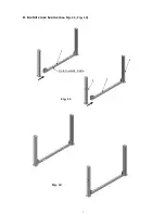
Page 11: ...7 D Install cross beams See Fig 11 Fig 12 Fig 11 Hole towards inside 1 3 2 3 Fig 12...
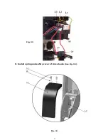
Page 25: ...21 O Install spring and safety cover of cross beam See Fig 34 Fig 34 3 3 3 8 40 3 2 Fig 33...
Page 27: ...23 IV EXPLODED VIEW Model PRO 14 Fig 36...
Page 28: ...24 3 73 74 CROSS BEAM CYLINDERS Fig 37 Fig 38...
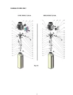
Page 29: ...25 MANUAL POWER UNIT Fig 39 220V 50HZ 1 phase 380V 50HZ 3 phase...
Page 39: ......

