28
VI. OPERATION INSTRUCTIONS
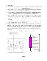
To lift vehicle
1.
Keep clean of environment near the lift;
2.
Drive vehicle to the Platform and put on the brake;
3.
Turn on the power and press the push button, raise the lift to the working position;
Note: make sure the vehicle is steady when the lift is raised.
4.
Press the Handle of release valve to lock the lift in the safety position. Make sure the
Safety device is locked at the same height.
To lower vehicle
1. Be sure the clearance of around and under the
lift, only leaving operator in lift area;
2. Press the push button, the lift will be raised for 3-5 seconds, and then press the
button of Manual-controlled air valve by hand to make sure the safety device
released, press the release valve handle by the other hand then the lift starts being
lowered automatically;
3. Drive away the vehicle when the lift is lowered to the lowest position;
4. Turn off the power.
VII.MAINTENANCE SCHEDULE
Monthly:
1.
Re-torque the anchor bolts to 150 Nm;
2.
Lubricate cable with lubricant;
3.
Check all cable connection, bolts and pins to insure proper mounting;
4.
Make a visual inspection of all hydraulic hoses/lines for possible wear or leakage;
5.
Lubricate all Rollers, Safety devices with 90wt. gear oil or equivalent.
Note: All anchor bolts should take full torque. If any of the bolts does not function for
any reason, DO NOT use the lift until the bolt has been replaced.
Every six months:
1.
Make a visual inspection of all moving parts for possible wear, interference or
damage.
2.
Check and adjust as necessary, equalizer tension to insure level lifting.
3.
Check the vertical of columns.
Summary of Contents for PRO-14
Page 1: ...FOUR POST LIFT PRO 14...
Page 2: ......
Page 4: ......
Page 11: ...7 D Install cross beams See Fig 11 Fig 12 Fig 11 Hole towards inside 1 3 2 3 Fig 12...
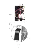
Page 25: ...21 O Install spring and safety cover of cross beam See Fig 34 Fig 34 3 3 3 8 40 3 2 Fig 33...
Page 27: ...23 IV EXPLODED VIEW Model PRO 14 Fig 36...
Page 28: ...24 3 73 74 CROSS BEAM CYLINDERS Fig 37 Fig 38...
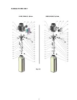
Page 29: ...25 MANUAL POWER UNIT Fig 39 220V 50HZ 1 phase 380V 50HZ 3 phase...
Page 39: ......


