background image


14 

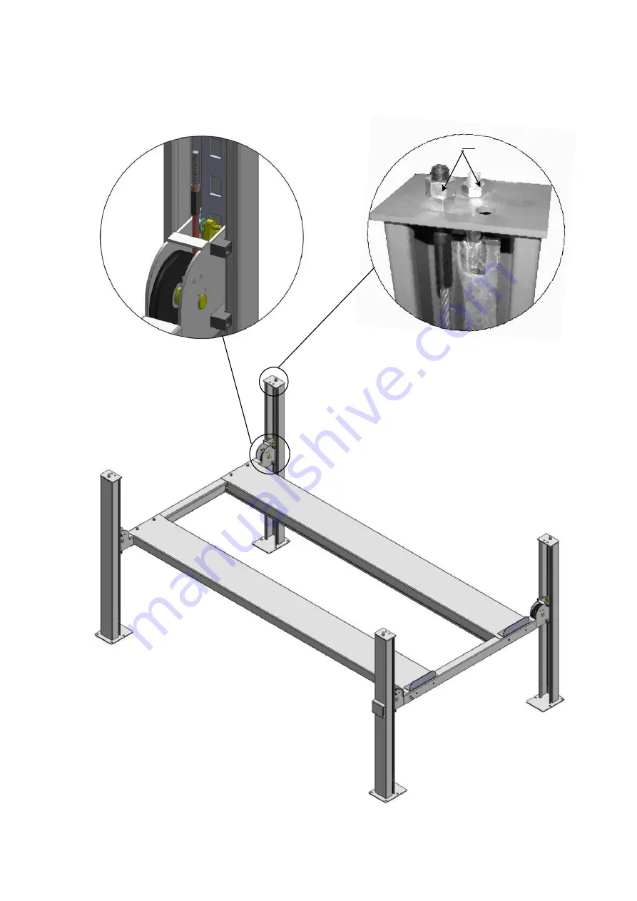
2. The cable goes through the cross beam to top plate of columns and be screwed with 

cable nuts

 (See Fig. 20).


Fig. 20


Cable goes between 
the big pulley and 

tension pulley


Cable pass through top 
plate and be screwed 

with cable nuts.


17 

Summary of Contents for 409-HP

Page 1: ...409 P 409 HP ...

Page 2: ...eatures and Specifications 1 Installation Requirement 2 Steps of Installation 3 Exploded View 26 Test Run 30 Operation Instruction 31 Maintenance 31 Trouble Shooting 32 Parts List 33 I PRODUCT FEATURES AND SPECIFICATIONS ...

Page 3: ...iamond platforms and adjustable safety lock ladders Optional kits Rolling jack with hand pump caster kits MODEL 409 P 409 HP SPECIFICATIONS Model Lifting Capacity Lifting Height Lifting Time Overall Length Inc Ramps Overall Width Width Between Columns Gross Weight Motor 409 P 9 000 lbs 73 5 8 45S 218 3 4 126 1 4 112 1 2 2130lbs 2 0HP 409 HP 9 000 lbs 85 1 2 53S 230 1 2 126 1 4 112 1 2 2172lbs 2 0H...

Page 4: ...UIRED Tape Measure 7 5m Hammer Level Bar English Spanner 12 Wrench set Carpenter s Chalk Screw Sets Pliers Lock Wrench Socket Head Wrench 12 13 14 15 17 19 24 30 3 5 6 8 B SPECIFICATIONS OF CONCRETE See Fig 3 Fig 2 ...

Page 5: ...tion and must be of test strength 3 000psi 210kg cm minimum 3 Floors must be level and no cracks C POWER SUPPLY The electrical source must be 2 0HP minimum The source cable size must be 2 5mm and in good condition of contacting with floor III STEPS OF INSTALLATION A Check the parts before assembly 1 Packaged lift and Hydraulic Power Unit See Fig 4 2 Open the outer packing carefully check the parts...

Page 6: ...s inside the powerside platform then remove the package stand 5 Move aside the parts and check the parts according to the shipment parts list See Fig 7 6 Open the carton of parts and check the parts according to the parts box list Fig 6 Powerside Platform Drive in Ramp Offside Platform Cross Beam Column Fig 5 Parts box 61 Fig 7 Shipment Parts List ...

Page 7: ...5 See Fig 8 7 Check the parts of the parts bag according to the parts bag list See Fig 9 B Use a carpenter s chalk line to establish installation layout as per Table 1 Fig 8 Fig 9 ...

Page 8: ...e Fig 10 Note Reserve space front and behind the installation site C Install cross beams See Fig 11 Fig 12 MODEL A B C 409 P 185 126 1 8 224 409 HP 196 7 8 126 1 8 233 7 8 B A C 1 Fig 10 Use a carpenter s chalk line to establish installation layout 2 ...

Page 9: ...7 D Install the Safety Ladders Fig 11 Hole towards inside 6 3 The powerside column need to be installed according to the installed position of the safety lock release handle Fig 12 ...

Page 10: ...ion Then install the safety ladder See Fig 13 2 Install Safety Ladders See Fig 14 Fig 13 Safety Ladder is inserted between Limited Pins of the cross beam Safety Ladder Limited Pin Limited Pin Unscrew a nut of the safety ladders Take off the cross beam plastic cover Insert the safety ladder from up to the bottom between the Limited Pins ...

Page 11: ... should be the same Safety ladder pass through the hole of the top plate then tighten the two nuts Fig 14 Fig 15 18 17 The lifting cross beam height should be fitted for installing the platform and its parts 1m height is recommended The safety device on the cross beam should lock into the safety ladders at the same level Lifting both cross beams to the same height ...

Page 12: ...atforms can rest into the cross beams slots See Fig 16 Install the power side platform and screw up the bolts Fig 16 Offset the cross beam lean outward when putting the powerside platform on the cross beams Offset the cross beam lean outward when putting the powerside platform on the cross beams Illustration for front pulley in powerside platform ...

Page 13: ...n install the lift according to the location Below is the installation for the side of cross beam B car in direction If choosing the side of cross beam A car in direction then install the tire stop plate to the other side 2 Powerside column can be installed at any position on customers requirement but the power unit must be installed near the side with the safety lock release handle Fig 17 car in ...

Page 14: ... level and adjusting with the shims See Fig 18 Fig 18 Level bar Install the bolts for the platform strengthen plate 33 9 10 32 Note DO NOT completely tighten the limit slide blocks Loosen 1 4 lap after tightening 4 29 30 31 Position the slide blocks along the bent edges of the columns Connect the slide blocks to the cross beam with bolts 34 ...

Page 15: ...les See Fig 19 NO Cable Length for 409 P inc connecting fitting 124 363 1 4 187 301 3 8 Length for 409 HP inc connecting fitting 132 3 4 383 1 4 194 3 4 321 1 4 Cable installation diagram A C B 35 36 37 38 Install the cylinder connecting plate as shown and pay attention to the direction of unfilled corner on the plate D Fig 19 A B C D ...

Page 16: ...goes through the cross beam to top plate of columns and be screwed with cable nuts See Fig 20 Fig 20 Cable goes between the big pulley and tension pulley Cable pass through top plate and be screwed with cable nuts 17 ...

Page 17: ...15 3 Illustration for platform cables See Fig 21 Fig 21 Cable 4 Cable 2 Cable 2 Cable 1 Cable 4 Cable 3 Cable 1 Cable 2 Cable 4 Cable 2 Cable 3 Cable 4 39 Hex Bolt M10 120 Cable 4 Cable 2 Limit block ...

Page 18: ...d device assy of cross beam A B Safety lock rotated Device assy Connecting bar 43 43A 45A 45 Safety lock rotated Device assy Fig 22 According to the above diagram Install lock release handle to the connecting bar with M8 35 bolts and washers on cross beam A According to the above diagram fix safety lock connecting bar and safety lock connecting assy by M8 35 bolts and washers on cross beam B ...

Page 19: ...the safety release handle 1 Install Power unit on the cross beam A the installation of connection tube as Fig 23 Car in direction Cross beam A Fig 23 Cross beam B 201 10 46 9 47 40 41 40 Fixing plate GUDI 42 Install M8 25 Socket bolt with washer to these two holes ...

Page 20: ...18 2 Install Power unit on the cross beam B See Fig 24 Car in direction Fig 24 Cross beam B 40 41 40 Fixing plate GUDI 42 Install M8 25 Socket bolt with washer to these two holes ...

Page 21: ...o avoid the oil hose scratched by cable 2 For power unit attached to the column of cross beam B See Fig 26 a d cylinder inlet port swing upward Oil return hose passed above the cable b 53 Fig 25 52 The oil hose and oil return hose pass through the protective hose and connect to the power unit 48 4 55 49 50 55 52 51 50 56 55 54 Oil return hose c Retainer a b c d 49A 49C ...

Page 22: ...and zero wire N to terminals of AC contactor marked L1 L2 respectively 2 Connecting the two motor wires to terminals of AC contactor marked T1 T2 3 Connecting A2 to L2 of AC contactor 4 Connect the two wire of the button switch to the terminals of AC contactor marked A1 L1 Motor wire connection 2 Connection Step See Fig 30 Fig 27 a b c d Fig 26 Circuit Diagram 按钮开关 220V KM QS L N SB UP KM 3 4 A2 A...

Page 23: ...spectively b Terminals 4 of control button is connected with terminals of AC contactor marked L1 wire 3 is connected with A1 terminals of control button M Install spring and safety cover of cross beam See Fig 28 N Install drive in ramp jack tray and plastic oil pans See Fig 29 59 57 58 60 Fig 28 ...

Page 24: ...ttach the drive in ramp O Install Rear wheel stop plates See Fig 33 After driving the vehicle on the lift take off the drive in ramp install rear wheel Fig 29 Screw the M16 30 bolts to the side hole of the cross beam Attach the drive in ramp with the bolts 63 7 65 65A ...

Page 25: ...amp position P Install Layer Board Assy for Drive in Ramp Take down the Drive in Ramp and put it in the platform and layer board assy See Fig 31 For optional kits installation 1 Install optional caster kits See Fig 32 Fig 30 64 Fig 31 ...

Page 26: ... Q Fix the anchor bolts 1 Prepare the anchor bolts See Fig 35 Fig 33 Fig 32 68 Motor fixing bracket on cross beam A Optional motor fixing bracket Motor fixing bracket on cross beam B 67 66 Fig 34 67 4 67 2 67 3 67 5 67 11 67 6 67 7 67 8 Spring washer Washer ...

Page 27: ...holes and install the anchor bolts Do not tighten the anchor bolts See Fig 36 Note The tightening torque for the anchor bolt is 150N m Anchor bolts driven into the ground at least 90mm IV EXPLODED VIEW Model 409 P 409 HP Fig 36 Drillin g Clearin g Expand 90mm Nut Fig 35 69 ...

Page 28: ...26 CROSS BEAM 3 1 201 3 4 7 9 12 13 15 14 11 10 5 6 8 62 2 Fig 37 ...

Page 29: ...27 CYLINDERS Manual power unit 220V 60Hz Fig 38 Fig 39 ...

Page 30: ...28 Illustration of hydraulic valve Manual hydraulic power unit 110V 60Hz single phase Fig 41 Fig 43 Fig 40 ...

Page 31: ...N 1 Fill the reservoir with Hydraulic Oil Note In consideration of Power Unit s Release valve Fig 41 Relief valve Plug Check valve Oil return port Oil Outlet Handle for Release valve Throttle valve Protective ring ...

Page 32: ... at the same time 5 Adjust the clearance between the column and the plastic slider of cross beam to about 2mm Do not tighten the bolts of the sliding block let the sliding block can be turned after installing the bolts 6 After finishing the above adjustment test running the lift with load Run the lift with platforms in low position first make sure the platforms can rise and lower synchronously and...

Page 33: ...s and then press the safety release handle make sure the safety device released press the release valve handle by the other hand then the lift starts being lowered automatically 3 Drive away the vehicle when the lift is lowered to the lowest position Take off the rear wheel stop plates and install drive in ramp then left the lift 4 Turn off the power VII MAINTENANCE SCHEDULE Monthly 1 Lubricate ca...

Page 34: ...e or check valve in damage 5 Low oil level 1 Reverse two power wire 2 Repair or replace 3 Repair or replace 4 Repair or replace 5 Fill tank Lift does not stay up 1 Release valve out of work 2 Relief valve or check valve leakage 3 Cylinder or fittings leaks Repair or replace Lift raises too slow 1 Oil line is jammed 2 Motor running on low voltage 3 Oil mixed with Air 4 Pump leaks 5 Overload lifting...

Page 35: ...209005 Self locking Nut 26 26 11 410090 Cylinder fixed ring 1 1 12 410081 Cylinder 1 0 410070 0 1 13 420626 Cable connecting plate 1 1 14 420014 Hex Nut 1 1 15 201005 Split Pin 1 1 201 410095 Manual power unit 1 1 17 420175A Hex nut 16 16 18 410022 Safety ladder 4 0 410073 0 4 19 420022A Pulley pin assy 2 2 20 420023A Washer 13 13 21 420024B Pulley 10 10 22 209034 Lock washer 10 10 23 420144 Washe...

Page 36: ...bolt 4 4 43 217005 Plastic ball 1 1 43A 209056 Self locking Nut 1 1 44 410025 Socket bolt 4 4 45 410026 Safety release handle 1 1 45A 410100 Extension release handle assy 1 1 46 209004 Rubber ring 4 4 47 209003 Hex Bolt 8 8 48 420166 900 Fitting 1 1 49 420243 Straight Fitting for cylinder 1 1 49A 420245 Straight Fitting 1 1 49B 209119 compensation valve 1 1 49C 201020 T fitting 1 1 50 410136 Oil h...

Page 37: ...2 Fixing plate for motor 1 1 Parts for optional caster kits See Fig 34 67 1 410042A Support bracket 4 4 67 2 209125 Hex bolt 16 16 67 3 209039 Lock washer 16 16 67 4 209022 Washer 16 16 67 5 209021 Hex nut 16 16 67 6 410035 Plastic wheel 4 4 67 7 410034 Connecting pin 4 4 67 8 209012 Hair Pin 8 8 Parts For Cross Beam See Fig 38 3 1 206024 Hex bolt 4 4 3 2 206032 Snap ring 2 2 3 2A 217020 Bronze bu...

Page 38: ...0 12 1 420059 Dust Ring 1 1 12 2 420060 Y Ring 1 1 12 3 410082 Head Cap 1 1 12 4 410083 O Ring 1 1 12 5 410084 Bore Weldment 1 0 410078 0 1 12 6 420064 Piston Rod 1 0 410079 0 1 12 7 410085 Pin 1 1 12 8 410086 Support Ring 1 1 12 9 410087 Y Ring 1 1 12 10 410088 Piston 1 1 Parts For Manual Power Unit 220V 60Hz single phase 1 81400180 Rubber Gasket 2 2 2 81400130 Start Capacitor 1 1 3 420148 Run Ca...

Page 39: ...1106 Ties 1 1 25 81400296 Magnet of power units 1 1 26 81400459 Filter net 1 1 27 10209069 Motor 1 1 28 81400266 Relief Valve 1 1 29 81400284 Inner Hex Iron Plug 1 1 30 81400452 Elastic latch 1 1 31 81400451 Handle For Release Valve 1 1 32 10209020 Plastic ball of rack handle 1 1 33 81400125 Release valve nut 1 1 34 81400124 Release valve spacer 1 1 35 81400450 Valve seat 1 1 36 070001 Release Val...

Page 40: ...38 AMGO HYDRAULIC CORPORATION Tel 803 505 6410 Fax 803 505 6410 1931 Jo Rogers Blvd Manning South Carolina USA ...

Page 41: ...39 Manual Part No 72147401 Revision Date 2017 10 ...

Reviews: