16
NO
NO
A2
A2
A1
T1
T2
T3
L3
L2
L1
M
~
G
N
L
外
接
电
源
按钮开关
N. Tighten all the hose fitting and fill the power unit with Hydraulic Oil.
In consideration of Hydraulic Power Unit’s durability and keep the equipment
running in the perfect condition, please use Hydraulic Oil 46#.
O. Install Electrical System
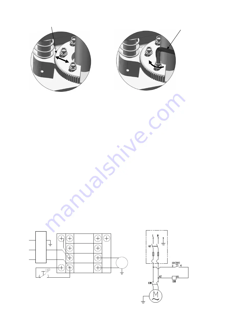
According to the circuit schematic, connect the power source on the data plate of Power
Unit.
Note: 1. For the safety of operators, the power wiring must contact the floor well.
2. Pay attention to the direction of rotations when using 380V, three phase motors.
Single phase motor
(See Fig. 27).
1. Connecting the two power supply lines (active wire
L
and neutral wire
N
) to
terminals of AC contactor marked L1, L2 respectively.
2. Connecting the two motor wires to terminals of AC contactor marked
T1, T2
.
3. Connecting
A2
to
L2
of AC contactor.
4. Terminal
4#
of control button is connected with terminals
A1
of AC contactor;
Terminal
3#
of control button is connected with terminals
L1
of AC contactor.
Fig. 27
Adjust the moon gear
Tighten the bolts
Fig. 25
Adjust gear and rack meshing.
Fig. 26
Lock the screws by wrench after the gear
and rack are in good meshing condition
单相
Po
w
er
so
ur
ce
Control button
AC contactor
Single Phase
Switch button
Summary of Contents for BP-10
Page 1: ...TWO POST LIFT Model BP 9X BP 10 ...
Page 4: ...2 Arm Swings View 2560mm 100 3 4 Fig 2 ...
Page 11: ...9 G Raise up the carriage and lock it in the same position of safety device see Fig 16 Fig 16 ...
Page 14: ...12 I Assemble oil hose assy See Fig 19 Fig 19 71 73 72 71 69 70 71 71 68 ...
Page 19: ...17 IV EXPLODED VIEW Model BP 9X BP 10 Fig 28 ...
Page 25: ...23 4 3 MANUAL POWER UNIT 071101 Fig 32 Manual Power unit 220V 60Hz ...


