26
3.
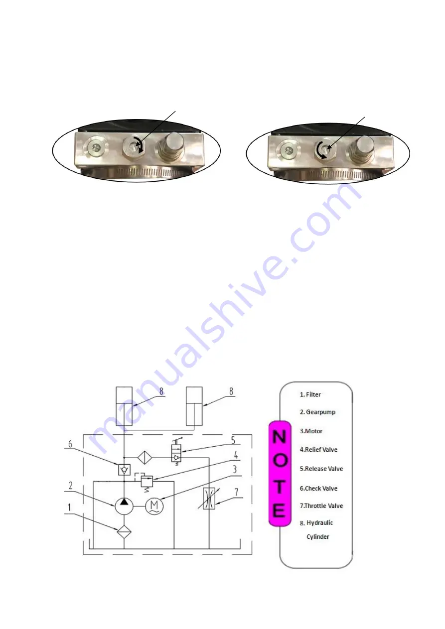
Adjust the lower speed
You can adjust the lower speed of the lift if needing: turn the throttle valve clockwise to
decrease the lower speed, counterclockwise to increase the lower speed.
(See Fig. 35)
4. Test with load
After finishing the above adjustment, test running the lift with load. Run the lift in
low position for several times first, make sure the lift can rise and lower
synchronously, the Safety Device can lock and release synchronously. And then test
run the lift to the top completely. If there is anything improper, repeat the above
adjustment.
NOTE: It may be vibrated when lifting at start, please lifting it with load for several
times, the air would be bled and the vibration would be disappeared automatically.
Hydraulic Schematic Diagram
Fig.35
Throttle valve
Clockwise to decrease the
lower speed.
Counterclockwise
to increase the lower speed.
Throttle valve
Fig. 36
Summary of Contents for BP-10
Page 1: ...TWO POST LIFT Model BP 9X BP 10 ...
Page 4: ...2 Arm Swings View 2560mm 100 3 4 Fig 2 ...
Page 11: ...9 G Raise up the carriage and lock it in the same position of safety device see Fig 16 Fig 16 ...
Page 14: ...12 I Assemble oil hose assy See Fig 19 Fig 19 71 73 72 71 69 70 71 71 68 ...
Page 19: ...17 IV EXPLODED VIEW Model BP 9X BP 10 Fig 28 ...
Page 25: ...23 4 3 MANUAL POWER UNIT 071101 Fig 32 Manual Power unit 220V 60Hz ...


