Page 11
Hard Drive Installation Instructions
CAUTION
Hard drives are extremely sensitive to
physical mishandling. Always keep the
hard drives protected from accidental
falls, banging, dust, or liquids.
WARNING
Never install or remove a hard drive when
the unit is powered on. As an extra
precaution, always unplug the power cord at
the power supply before removing or
installing the hard drive.
1. Unlock and open the front door.
2. Make sure the jukebox is turned off and
unplugged.
3. Partially install the 2 provided thumbscrews
in the mounting holes on each side of the
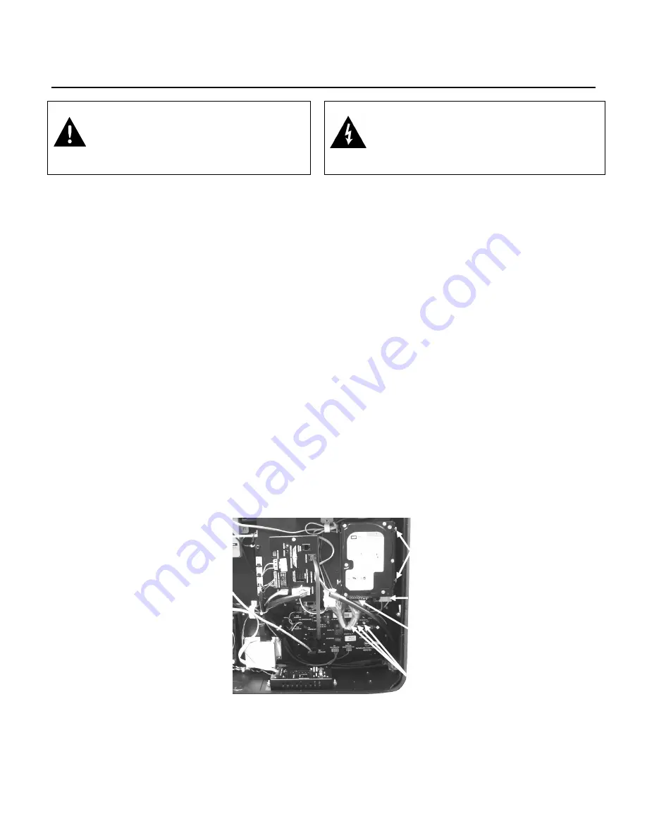
hard drive (see
Figure 9-B
), leaving about
1/16 of an inch between the hard drive and
the thumbscrew.
4. Install the hard drive into the bracket in the
lower right-side of the jukebox (as shown in
Figure 9-B
) and tighten the thumbscrews on
the left side of the hard drive, leaving the
thumbscrews on the right side of the drive
loose.
5. Locate the free ends of the 4-pin hard drive
power cable and the 2 x 20-pin IDE cable.
These cables will be routed out of the bottom
of the computer core near the hard drive.
Connect these cables to the hard drive as
shown in
Figure 9-B
.
6. Plug in the power cord and turn on the
jukebox by flipping the toggle switch on the
power supply (see
Figures 1-B and 2-B
) to
the ON position.
Connection Rules
The first time you boot up the jukebox with your hard
drive, a 30-day grace period will begin. If at the end
of these 30 days your jukebox has not connected to
the AMI Entertainment® Network to validate its
licenses, the jukebox will cease to play selections.
In order to properly connect to the network, a valid
trigger code must be entered in the software. To
enter your trigger code, press the SERVICE button
on the Rowelink Controller (see
Figure 9-B
). On the
touchscreen, touch
System Setup
and then touch
Enable/Extend Features
. Enter the trigger code
provided to you with your hard drive and then press
the
Send Code
button. The jukebox will display
“Valid trigger code entered” if it accepted your entry.
After the jukebox has made its initial connection to
the AMI Entertainment Network, it must continue to
connect at least once every 7 days to validate its
licenses or the jukebox will cease to play selections.
Figure 9-B – Inside View of Lower-Right Side of Cabinet
THUMBSCREWS
SECURING HARD DRIVE
(BOTH SIDES)
4-PIN POWER CABLE
ATTACHED TO HARD DRIVE
2 x 20-PIN IDE CABLE
ATTACHED TO HARD DRIVE
“SERVICE”, “CALIBRATE”,
AND “POWER” BUTTONS ON
ROWELINK CONTROLLER
Summary of Contents for Rock-Star Lx
Page 1: ...22022611 Rev C Installation Owner s Manual ...
Page 2: ......
Page 25: ...Page 23 Section D Service Maintenance Routine Maintenance Schedule ...
Page 30: ...Page 28 Front Door INSIDE VIEW ...
Page 34: ...Page 32 Inside and Outside Cabinet INSIDE CABINET LOCK PARTS 26 25 23 22 24 ...
Page 41: ...Page 39 Harnesses 10 34022338 11 34022342 12 34033235 13 34037940 14 34100303 15 34099901 ...


