Outdoor LoRa Data Logger
38
2.4 Modbus Configuration
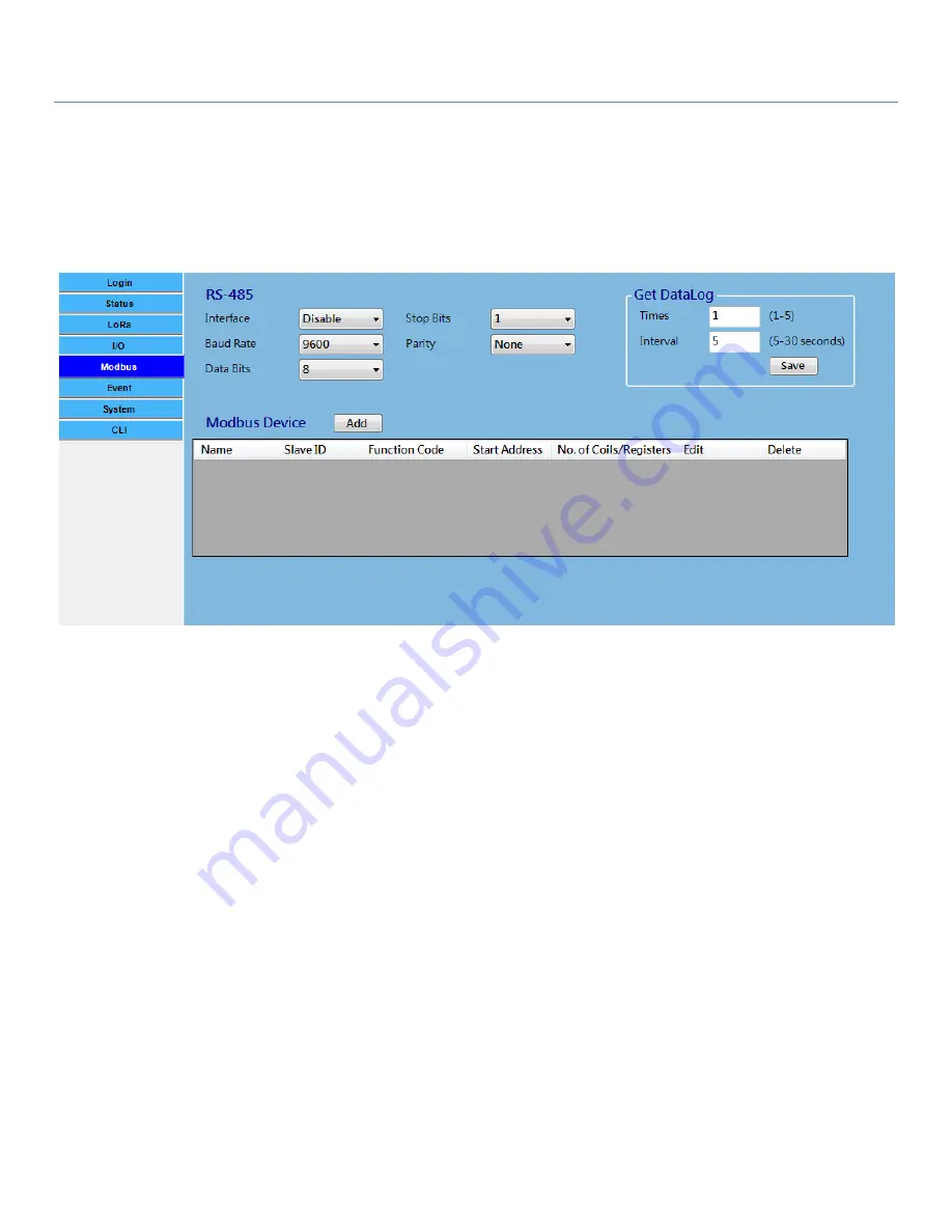
The OOT550 series product provides one RS-485 port for connecting with Modbus RTU Slave devices. It can
handle up to three sets of cascaded Modbus devices.
RS-485 Serial Port Configuration
Prior to configure how to access the Modbus devices, you need to define the physical communication port
first. In RS-485 configuration, you can enable the
Interface
, and then select desired values for
Baud Rate, Data
Bits, Stop Bits
, and
Parity
settings.
Interface
: By default, the interface is disabled. You can enable it and set the interface parameter to
comply with the devices to be connected.
Baud Rate
: Select the appropriate baud rate for serial device communication. It can be 1200 / 2400 /
4800 / 9600 / 19200 / 38400 / 57600 / 115200. It depends on the cable length and the
installed environment. The longer cable length will result in lower baud rate for it. By
default, 9600 is selected.
Data Bits
:
Select 7 or 8 for data bits. 8 is selected by default.
Stop Bits
:
Select 1 or 2 for data bits. 1 is selected by default.
Parity
:
Select None / Even / Odd for Parity bit. None is selected by default.
Modbus Device Configuration
Click
Add
button to enter required information or values for each Modbus device. The data fields are
Name
,
Slave ID
,
Function Code
,
Start Address
, and
No. of Coils/Registers
.
When you entered the required settings
for a Modbus device, click
Confirm
button to update the information to the device list. In addition, you can
also click
Edit
or
Delete
button to modify the information or values in the device list.


