background image

Outdoor LoRa Data Logger


39 


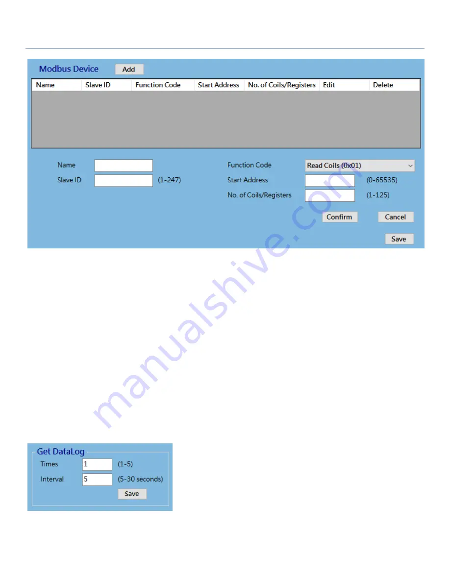
Name

:  

Enter a name as the identifier of the Modbus RTU slave device. 

Slave ID

:  

Specify a unique ID for the slave device. It can be 1 - 247. 

Function Code

: Specify a certain read function for the Data Logger to issue and record the responses 

from slave device. It can be 

Read Coils (0x01)

Read Discrete Input (0x02)

Read Holding 

Registers (0x03)

, and 

Read Input Registers (0x04)

.  

Start Address

: Enter the Start Address of registers to apply with the specified function code. It can be 0 

- 65535. 

No. of Coils/Registers

: Enter the number of coils (registers) to apply with the specified function code. It 

can be 1 - 125. 


Check  the  document  of  the  connected  Modbus  devices  for  how  to  get  the  desired  data  through  Modbus 
commands. 
Finally, click 

Save

 button to store the configuration in the device. 

 
More  over,  you  can  specify  the  behavior  of  data  logging  from  the  Get  DataLog  window.  Once  the  schedule 
timeup, the Data Logger will get and log all the Modbus RTU values.  


Times

:   Specify the data logging counts for each schedule timeup. 

Interval

: Specify the time interval between two data logging. 


Summary of Contents for OOT550-DL3B2

Page 1: ...LPWA LoRa Outdoor LoRa Data Logger OOT550 DL3B2 User Manual ...

Page 2: ...over 10 1 6 2 Install Battery 12 1 6 3 Connecting to External Devices 15 1 6 4 Connecting USB cable for PC Configuration Tool 24 1 6 5 Power On the OOT550 25 1 6 6 Setup with Windows based Configuration Tool 27 1 6 7 Device Mount and Screw Back the Top Cover 29 Chapter 2 Device Configuration 30 2 1 Device Status 30 2 2 LoRa Configuration 31 2 3 I O Configuration 35 2 4 Modbus Configuration 38 2 5 ...

Page 3: ...he OOT550 DL has ultra low power consumption which allows it to operate on a single battery for years 1 Main Features Simple device with various interfaces AI DI RS485 for IIoT field data acquisition Transfer of field data to associated LoRa Network Server at pre defined time interval or on an event at the site Internal battery powered design for easy deployment Low power consumption and work with...

Page 4: ...er 4 1 2 Contents List 1 2 1 Package Contents Standard Package Items Description Contents Quantity 1 OOT550 DL3B2 Outdoor LoRa Data Logger 1pcs 2 Battery 1pcs 3 Cable Tie 2pcs 4 AI Jumper 3pcs 5 Water Dust proof Stopper 3pcs ...

Page 5: ...Outdoor LoRa Data Logger 5 1 3 Hardware Configuration Front View M16 Water Dust proof Connectors with two hole cable gland inserted ...

Page 6: ...dication LED Icon Indication LED Color Description LED Device Status Blue Red Steady OFF Device is powered off Blue Flash per second Device is boot up Red Flash Battery Low Blue and Red Steady ON Device is in Recovery mode or FW Upgrading ...

Page 7: ...or device configuration 1 5 2 WARNING Only use the Battery that comes with the package or the external DC Power Supply that complies to device spec Using a different voltage rating power adaptor is dangerous and may damage the product DO NOT remove or repair the control board by yourself If the product is too hot or malfunctioning turn off the device and have it repaired at a qualified service cen...

Page 8: ...equipment and receiver Connect the equipment into an outlet on a circuit different from that to which the receiver is connected Consult the dealer or an experienced radio TV technician for help FCC Caution Any changes or modifications not expressly approved by the party responsible for compliance could void the user s authority to operate this equipment This transmitter must not be co located or o...

Page 9: ...F Exposure Statements The antenna of the product under normal use condition is at least 20 cm away from the body of user 4 Unit Mounting Notice The product is suitable for mounting at heights 2m approx 6 ft or in a cabinet Ensure the unit is fixed tightly to reduce the likelihood of injury due to exposure to mechanical hazards if dropped 5 Manufacture Information Manufacture Name AMIT Wireless Inc...

Page 10: ... battery ER18505 A Size or external 5V 12V DC power This section describes how to install and configure the hardware 1 6 1 Open the Top Cover The OOT550 series is design for universal data logging use There are various interfaces for connecting to your field devices and enclosed with an IP65 grade enclosure All the connection cables to the field devices must be wired properly through the M16 conne...

Page 11: ...e required configuration and need to Power Up the device 3 The RESET button provides user with a quick way to reboot the device Status LED J1 Micro USB for Device Config Nano SIM Socket reserved CON4 16 pin spring type Terminal Block for I Os trigger CON3 2x3 headers for AIs w o Jumper Voltage w Jumper Current S2 Power Switch ON OFF CON2 8 pin spring type Terminal Block for RS485 ext power wake up...

Page 12: ...or LoRa Data Logger 12 1 6 2 Install Battery Step 1 Insert the two cable ties and go through the battery stands Step 2 Load the battery over the stands as the illustrated and pull tightly for each cable tie ...

Page 13: ...battery is a hazardous waste and should be recycled or brought to a hazardous waste disposal facility 4 Battery Replacement You can purchase a new full power battery and replace it by yourself The Battery Specification and Power pin must be compliant to the Original Design A 4000mAh 3 6V Li SOCL2 battery ER18505 A Size with power cable B Re use the power connecter Red pin for V and Black pin for G...

Page 14: ...ecification If you purchase the battery from 3rd party please make sure it comply to the following electrical characteristics Not only Nominal Capacity and Voltage but also Max Continuous Current andf Max Pulse Capacity specifications are important ...

Page 15: ...xternal devices As indicated in the I O pinout sheet you can easily find out the pin location and connect to your devices with appropriate conductive cables However there are only two dual hole M16 water dust proof connectors for you to route the conductive cables out of the enclosure That is up to four cables can be routed to connect external devices ...

Page 16: ... terminals b Remove the external part of the M16 connector c Run the cable through the external parts as indicated below Step 2 a Place the tinned terminal over the connector b Use a flathead screwdriver and push down the clip c Insert the tinned terminal to very bottom d Release and verify the terminal is well locked ...

Page 17: ...talled properly 2 However if you intend to run more than two cables through the M16 connector or IP65 is not so critical for the installation you can decide not to put the cable glands and skip step 1b 1d for more IO flexibility Step 1 a Just keep required length of cable inside the enclosure b Insert the first cable gland part c Insert the second cable gland part d Insert the stopper if there is ...

Page 18: ...ware configuration is mandatory CON3 is dedicated for AI configuration There are 3 sets of jumper headers one for each AI port AI1 AI2 AI3 Without Jumper Voltage mode factory default With Jumper Current mode You have to put the Jumper manually Pinout Definition CON4 Pin1 Pin2 Pin3 Pin4 Pin5 Pin6 Pin7 Pin8 3 6Vout GND AI1 GND AI2 GND AI3 GND Note 3 6Vout CON4 1 is only valid when external power sou...

Page 19: ... Logger 19 Example of AI Connection Diagram If the signal range of your device will run out off the design spec of OOT550 you have to add a certain scaling circuit to prevent overflow readings and even damage the OOT550 ...

Page 20: ... either Pulse counter mode or just a Dry contact Since the OOT550 can not detect what kind of device is connected to not only hardware configuration CON4 is required but also software configuration is mandatory Pinout Definition CON4 Pin9 Pin10 Pin11 Pin12 Pin13 Pin14 Pin15 Pin16 DO DO DI1 DI1 GND DI2 DI2 GND Digital I O Specification I O Specification Digital Input Isolated Trigger Voltage high L...

Page 21: ...Outdoor LoRa Data Logger 21 Example of Connection Diagram DO ...

Page 22: ... the time the OOT550 data logger operates under sleep mode with ultra low power consumption design At that time no one can wake it up till the schedule time out If you still have to wake it up for some unexpected reason for example to change software configuration or upgrade new firmware there is a manually wake up mechanism for such kind of maintenance situation You can connect an external magnet...

Page 23: ...ctly if there is available DC power source at the installation site Pinout Definition CON2 Pin1 Pin2 Pin3 Pin4 Pin5 Pin6 Pin7 Pin8 GND RS 485 D B RS 485 D A GND PWR1 5V 12V PWR1 5V 12V GND WakeUp External DC Power Supply DC 5 12V Max Power Consumption 5W 5V 1A You can just connect the external DC Power to Pin4 Pin5 at CON2 Pin6 Pin7 are just duplicated pins you can just ignore it or provide power ...

Page 24: ...figuration procedure To make the OOT550 operate properly in according to attached external devices you have to further configure software settings from a PC configuration tool The OOT550 provide one micro USB port J1 for device configuration You have to connect a USB cable to the Configuration Port at J1 and the USB port for PC NB that will run the configuration tool ...

Page 25: ...wer on the OOT550 Please make sure the power source is properly installed For Battery Power Battery power cable is plugged onto the Power Socket CON1 and Power Source Jumper J6 is placed at the right side BAT For External DC Power External DC power cable is inserted into the external DC Power Port CON2 and Power Source Jumper J6 is placed at the left side EXT ...

Page 26: ...ED it starts with RED light LED1 and BLUE light LED2 for 1 2 seconds After a while LED1 and LED2 will turn to OFF state and the device is booting up Finally It will get reay and you can see the LED2 with BLUE light flashing once per second Power OFF Boot up and get ready Note If the OOT550 is powered with battery source the LED will be forced to OFF state while the device get into sleep mode ...

Page 27: ...tion Tool you will see the login dialog Click the drop down menu next to the Serial Port Choose the COM port that is bound to the OOT550 console port and then click the Connect button If you are not sure which COM port is the correct one please check the Device Management setting for the PC NB find out the device named Prolific PL2303GL USB Serial COM Port COMx from the Bluetooth and Other Devices...

Page 28: ...to prevent unexpected battery power loss Restore the prepared configuration file and quickly edit the settings unique to a certain device If the connection succeeded a list of menu items appears on the left side under the Login Tab Now you already logged in to the OOT550 console and you can proceed with the required software configuration steps one by one Refer to the following Chapter for the det...

Page 29: ...er Off the OOT550 and remove the USB cable 2 Mount the OOT550 base enclosure on the planned location 3 Make sure all the wiring cables are running in position through the M16 connectors 4 Fasten tightly the external parts on the M16 connectors holding the internal cables to prevent from twisted along with the cable gland with care 5 Power On the OOT550 and wait until the Status LED becomes BLUE li...

Page 30: ...ight hand side If the device status doesn t appear or you want to get the updated status click Status Refresh button located at the lower right corner to refresh the status immediately You can see the Device Information Device Name Series No and Firmware Version I O Connection Status Analog Input 1 3 Digital Input 1 2 Digital Output and Modbus Power Information Power Source and Battery Status and ...

Page 31: ...age you can configure the channel activation settings and MAC Layer settings Channel Configuration There are Channel Group 1 and 2 It will show the supported Sub Band depend on the area of the LoRa specification Channel Freq will show the detail frequences of the selected channel ...

Page 32: ...firm Specify whether the TX Confirm ACK response from network server is applied or not for each data uplink transmission By default Confirm is selected Un Confirm No ACK response is required The LoRa Node won t check whether the transmitted data is received by network server or not The data will be sent out only once Confirm An ACK response is required The LoRa Node will listen whether the transmi...

Page 33: ...x digits Device Address You can provide it for registering to a network server with ABP activation NwkSKey This is a 128 bit 32 Hex digits Network Session Key You can provide it for registering to a network server with ABP activation AppSKey This is a 128 bit 32 Hex digits Application Session Key You can provide it for registering to a network server with ABP activation Finally click Save button t...

Page 34: ...lt 300 seconds is configured Finally click Save button to store the configuration in the device Note DO NOT choose the Class C device type while it is powered by internal battery The device won t get into sleep mode if it is configured as Class C device and it will continuously drain away the battery power even it is idle and just listens for the command from network server ...

Page 35: ...tion the AI value read from A D converter can be further transform to a physical value for the real world like the temperature or water level You can specify a simple data conversion formula with the base fromat Physical Value Read Value Op 1 X Op 2 Y where Read Value the input value ex 7 5V or 12 4mA for a certain AI signal Op 1 and Op 2 both op can be or X and Y both values can be any real numbe...

Page 36: ...e slot Finally click Save button to store the configuration in the device Prior to store the I O settings the following dialog will appear for you to double confirm the settings of Analog Input type that the H W configuration and S W configuration are consistent After you confirmed the settings are correct click Yes button to store the configuration in the device More over you can specify the beha...

Page 37: ...logger will issue Battery Low event to remote server if it detects the battery voltage approached to the Low threshold The frequency depends on the Remote Server Schedule rule Each time when the data logger is waked up to send the stored log to remote server and if the Battery Low threshold is triggered the data logger will automatically issue a Battery Low event So when the administrator noticed ...

Page 38: ...ate for serial device communication It can be 1200 2400 4800 9600 19200 38400 57600 115200 It depends on the cable length and the installed environment The longer cable length will result in lower baud rate for it By default 9600 is selected Data Bits Select 7 or 8 for data bits 8 is selected by default Stop Bits Select 1 or 2 for data bits 1 is selected by default Parity Select None Even Odd for ...

Page 39: ... to apply with the specified function code It can be 0 65535 No of Coils Registers Enter the number of coils registers to apply with the specified function code It can be 1 125 Check the document of the connected Modbus devices for how to get the desired data through Modbus commands Finally click Save button to store the configuration in the device More over you can specify the behavior of data lo...

Page 40: ...ton to edit a specific event trigger For each event rule If condition then action you have to specify the condition part min hold time and the action part Condition part condition 1 AND OR condition 2 min Hold Time Above Condition remains TRUE for at least Thold condition hold time Action part make DO High DO Low or set Tirgger Schedule event flag till the condition FALSE Name Specify a name as th...

Page 41: ... The supported event action can be DO High or DO Low Select one action for each event rule When the event happens condition TRUE for the pase Thold duration the specified action will be take accordingly Enable Check Enable to activate the event rule Finally click Save button to store the configuration in the device Warning It is NOT recommended to use battery power to power on the OOT550 while eve...

Page 42: ...nd wait a while for the device to reboot Configuration Backup Restore In addition to the factory default settings you can also customize a special configuration setting as a customized default value With this customized default value you can reset the device to the expected default setting if needed Click Backup button to store the device configuration settings into a configuration file bin for la...

Page 43: ...the new firmware to the device DO NOT turn off the Data Logger or disconnect the console cable while upgrading new firmware it is very likely to damage the device Once the Firmware Upgrade completed the device will be reboot with the new firmware immediately System Time System time is a vital element for the LoRa Node Both data logging and data uploading tasks need to be triggered at a certain tim...

Page 44: ...gger 44 2 7 CLI Console Log The system console log will show at this configuration page It can help to monitor the system operation and event When some issue happens capture this console log and consult with device vendor ...

Page 45: ...byte i e Length of Command Total Length Data Data accompanied data bytes for the issued command Checksum Checksum byte for the complete command stream Command Total Length Data Direction The MSB of the Command code is defined as a Direction bit 0 for uplink direction and 1 for downlink For example command code 0x01 is an uplink command issued from a LoRa node to network server and 0x81 is a downli...

Page 46: ...Outdoor LoRa Data Logger 46 for i 0 i len i ret buf i return ret ...

Page 47: ... limit on the payload size This command may not be used for some Modbus device configuration that has many registers to read For example the packet 0115010000010100000901030300FA03C8DB64000093 is composed of Command byte 0x01 Total Length 0x15 Checksum 0x93 Data 010000010100000901030300FA03C8DB640000 where DI 1 length 0x01 value 0x00 DI 2 length 0x00 Nothing AI 1 length 0x01 value 0x01 AI 2 length...

Page 48: ... i Identifier for each input port Only those enabled input ports will appear in the payload DI 1 0x10 DI 2 0x11 AI 1 0x30 AI 2 0x31 AI 3 0x32 Modbus 1 0x50 Modbus 2 0x51 Modbus 3 0x52 Data i Length the data length of the corresponding input port Data i Value the data of the corresponding input port For example the packet 020E3002000031020000320200003D is composed of Command byte 0x02 Total Length ...

Page 49: ...nput port Only those enabled input ports will appear in the payload DI 1 0x10 DI 2 0x11 AI 1 0x30 AI 2 0x31 AI 3 0x32 Modbus 1 0x50 Modbus 2 0x51 Modbus 3 0x52 Data i Length the data length of the corresponding input port Data i Value the data of the corresponding input port For example the packet1 030A1002010231021F3307 Packet2 030D500901030300FA03C8DB64D8 are composed of Command byte 0x03 Packet...

Page 50: ...work server is asking for the LoRa node to get the status data of all input ports Note 1 There is maximum limit on the payload size This command may not be used for some Modbus device configuration that has many registers to read For example the packet 810283 is composed of Command byte 0x81 Total Length 0x02 Checksum 0x83 ...

Page 51: ...0x82 Total length Checksum 1 byte 1 byte 1 byte Command 0x82 Purpose A network server is asking for the LoRa node to get the status data of all enabled input ports For example the packet 820280 is composed of Command byte 0x82 Total Length 0x02 Checksum 0x80 ...

Page 52: ...he corresponding output port Data Value the data of the corresponding output port For a Modbus type port the data format is composed of Slave ID Function call Start Address Data Length Data 1 byte 1 byte 2 bytes 2 bytes 50 bytes Example1 the packet 8405700101F1 is composed of Command byte 0x84 Total Length 0x05 Device ID 0x70 Port DO 1 Data Length 0x01 Data Value 0x01 Checksum 0xF1 Example2 the pa...

Page 53: ...rning 0x70 Total length Checksum 1 byte 1 byte 1 byte Command 0x70 Purpose A LoRa node is alerting to the network server with low battery power warning For example the packet 700272 is composed of Command byte 0x70 Total Length 0x02 Checksum 0x72 ...

Reviews: