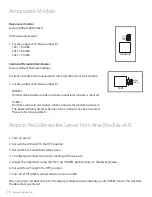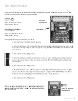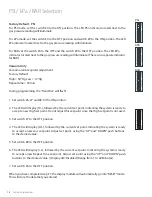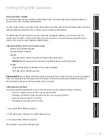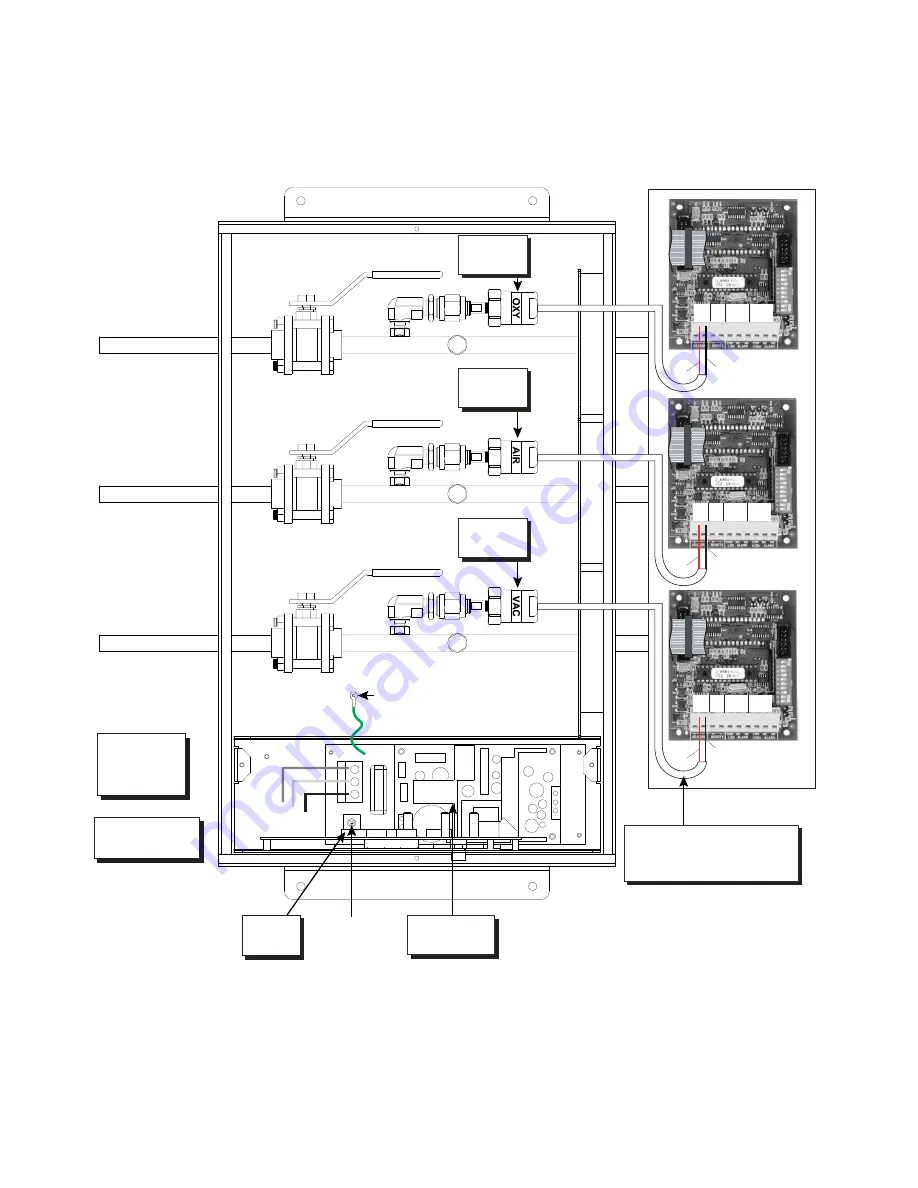
Appendix C
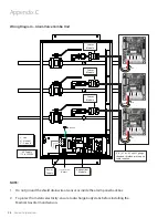
Wiring Diagram – Alarm Valve Combo Unit
Black
Red
SENSOR
+ -
REMOTE
+ -
COM NC NO
HIGH
ALARM
COM NC NO
LOW
ALARM
Black
Red
SENSOR
+ -
REMOTE
+ -
COM NC NO
HIGH
ALARM
COM NC NO
LOW
ALARM
Black
Red
SENSOR
+ -
REMOTE
+ -
COM NC NO
HIGH
ALARM
COM NC NO
LOW
ALARM
AC Supply
115 to 220 VAC
Power
Supply
L - Live
N - Neutral
G - Ground
Toggle Switch
ON/OFF
Ground
G
N
L
6"-8” [0.1 m - 0.2 m] #22 gauge
stranded, shielded twisted pair
cable supplied
Sensor
Module
Sensor
Module
Sensor
Module
Annunciator
Module
NOTE:
1. Do not ground the shield drain wire at sensor or inside the alarm panel back box
2. To protect from static electricity, ensure to discharge body static before installing the
Medical Gas Alarm and sensors
26
Amico Corporation

