background image

Operating & Maintenance Manual

Alert-2 Microprocessor Based
Digital Alarm System v6.3

Summary of Contents for Alert-2

Page 1: ...Operating Maintenance Manual Alert 2 Microprocessor Based Digital Alarm System v6 3...

Page 2: ...k Module 3 Compact Display Module 4 Sensor Module 4 Master Alarm 4 Master Nema 4 Status Module 4 Computer Interface Module 4 Installation 5 6 The Alarm Box 5 For Local Sensor Only 5 Standing Pressure...

Page 3: ...ng Gas Identification Switches 13 Chart of Gas Specific Settings of Dip Switches 14 Master NEMA 4 Status Module 14 16 Repeat Alarm 14 Signal Input Selection 15 Maintenance Mode 15 16 Troubleshooting G...

Page 4: ...gram Compact Display Module Remote Sensor Appendix F 35 Wiring Diagram Compact Module to Master Appendix G 36 Wiring Diagram Abnormal Condition Appendix H 37 Wiring Diagram Master NEMA 4 Module Append...

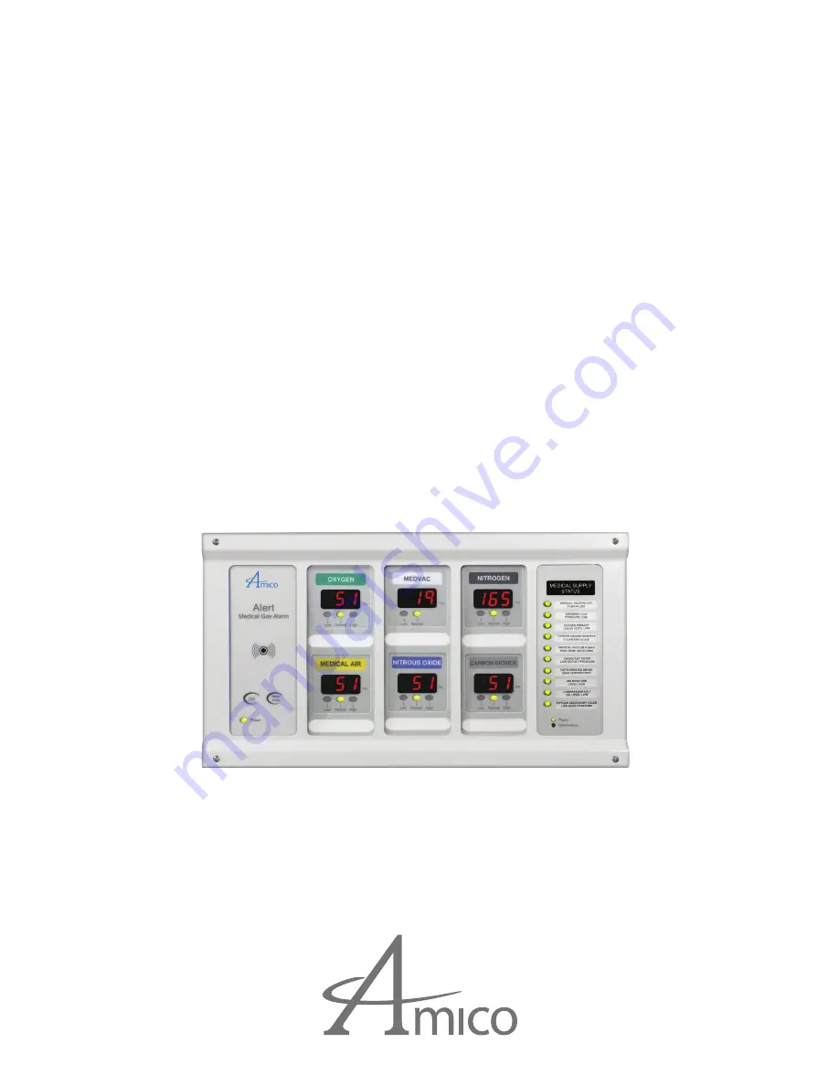
Page 5: ...System ALERT 2 incorporates the latest microprocessor technology for alarm and surveillance systems The alarm has been designed to provide user flexibility and reliability This manual will enable the...

Page 6: ...I kPa or BAR display switch selected Self diagnostic circuitry with error display for problem identification Highly accurate Solid State Pressure piezo resistive transducer Adjustable repeat alarm 1 t...

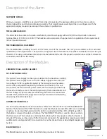
Page 7: ...on to another Amico Alarm or a Building Management System BLANK MODULE The Blank Module is used as a filler board for future provisions of the alarm Description of the Alarm A m i c o M i c r o p r o...

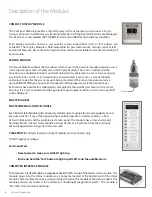
Page 8: ...displayed on the Display Module The sensor module shall be housed in an anodized aluminum and nickel plated brass enclosure to act as a barrier against any interference and it is also temperature comp...

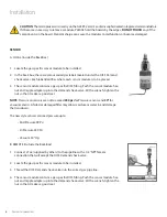
Page 9: ...alve by overheating the lower portion of the copper pipe When the brazing of pipe stubs has been completed the system can be pressure tested STANDING PRESSURE TEST Perform a standing pressure test on...

Page 10: ...s specific DISS fitting Push the sensor module hex nut and nipple adapter up into the demand check valve With a wrench tighten the nut so that it makes a good seal Installation A m i c o M i c r o p r...

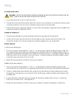
Page 11: ...gauge stranded shielded twisted pair cable One wire is Red positive and the other wire is Black negative Connect the wires to the display module as shown in Appendix D Take the Red wire fromthe sensor...

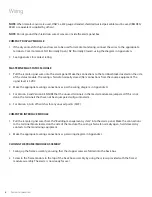
Page 12: ...5 VDC 2 Make the appropriate wiring connections as per the wiring diagram in Appendix H 3 For Version 3 and Version 4 ENSURE that the unused terminals in the master module are jumpered If this is not...

Page 13: ...u had entered Annunciator Module P a g e 1 6 THE ANNUNCIATOR MODULE NOISE LEVEL CONTROL Factory Default 90 Decibles To decrease noise level 1 Locate jumper at J5 Move jumper to LVL1 90 dBa LVL2 80 dBa...

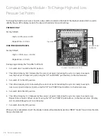
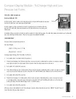
Page 14: ...High set point Adjust set point using the UP and DOWN push buttons to the desired value 3 Set switch 7 to the OFF position 4 The LED will display LO followed by the current set point Indicating the s...

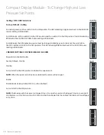
Page 15: ...6 7 and 8 to the ON position 2 The LED will display HI followed by the current set point Indicating the system is ready to accept a new High set point Do not adjust this set point since the High set...

Page 16: ...he LED indicating BAR located next to the VACUUM source reading will illuminate COMMON SETTINGS FOR PRESSURE AND VACUUM Repeat Alarm Enable Disable Factory Default Disable Disable Set switch 5 to the...

Page 17: ...odule is now in the default mode SETTING GAS IDENTIFICATION SWITCHES NOTE DO NOT tamper with switches 1 2 and 3 on the dip switch Tampering with these positions will result in an error message being d...

Page 18: ...applies to the Master NEMA 4 alarm Chart of Gas Specific Settings of Dip Switches Master NEMA 4 Status Module P a g e 2 1 CHART OF GAS SPECIFIC SETTINGS OF DIP SWITCHES ON ON ON ON ON ON ON ON 4 4 4 4...

Page 19: ...ow hospital personnel to identify loose wiring or faulty source equipment By putting the master module into Latch mode any alarms received even transient ones will be latched on so that maintenance pe...

Page 20: ...ip switch is responsible for activating and deactivating each individual corresponding channel on the Masterboard ALL CHANNELS ACTIVATED ALL CHANNELS DEACTIVATED NOTE Version 4 Jumper any unused point...

Page 21: ...erminal block above the transformer Ensure that 115 VAC or 220 VAC is being supplied Fuse is blown Check the fuse The fuse is located on the upper right corner of the system power supply Replace the f...

Page 22: ...or module Alarm condition exists but LED s are not illuminating Display module not properly calibrated 1 Ensure that the system was properly ordered Factory default settings Mid Pressure Hi Pressure 6...

Page 23: ...t below the Low set point or vice versa Recalibrate the High and Low setpoint to proper values 10 11 E04 Incorrect type of Sensor connected i e 250 Psi sensor on a 100 Psi range Connect the correct Se...

Page 24: ...eLetters XX Define the Number of Functions 10 10 Functions 20 20 Functions TheLetter L Represents the Langauge E English CSA NFPA F French CSA S Spanish NFPA N Nema The Letter L Represents the Languag...

Page 25: ...gang back box 6 modules A2DRU XXXXXX 4 gang back box 8 modules A2DRU XXXXXXXX 7 gang back box 10 modules A2DRU XXXXXXXXXX 7 gang back box 12 modules A2DRU XXXXXXXXXXXX 7 gang back box Model Numbers R...

Page 26: ...BINATION ALARM Use the Model number for the Area Alarm and add M for each Master module Example 3 Gases English ISO Remote Local Sensors Oxygen Vacuum Medical Air and 2 Master Modules A2DRE OVAMM 1 2...

Page 27: ...ster alarm module English 10 points A2P MAST CB Master circuit board Assembly Alert 2 A2P BLANK Alert 2 alarm module blank filler A2P BOXASS 4 Alarm back box Assembly 4 station Alert 2 A2P BOXASS 7 Al...

Page 28: ...2P COMPAC T E CO2 COMPACT TOP AREA BOARD CO2 ENG A2P COMPAC B E CO2 COMPACT BOTTOM AREA BOARD CO2 ENG A2P COMPAC T E IAR COMPACT TOP AREA BOARD INST AIR ENG A2P COMPAC B E IAR COMPACT BOTTOM AREA BOAR...

Page 29: ...Product A2P CONKIT TRITEC 1 Conv 1 Gas Tri Tech Beconmedes PB Mega Model Number Description S DIS KIT OXY DISS Demand Check Nut and Nipple OXY S DIS KIT AIR DISS Demand Check Nut and Nipple AIR S DIS...

Page 30: ...rporation 10 254 A 4 102 9 229 1 1 4 32 5 8 16 B Number of Display Modules A B Gang From 1 to 3 modules 14 356 15 381 4 From 1 to 6 modules 24 610 25 635 7 Inch mm MASTER ALARM Mounting Bracket 7 178...

Page 31: ...14 356 15 381 4 From 1 to 6 modules 24 610 25 635 7 COMPACT ALARM Inch mm 1 65 42 1 65 42 1 65 42 1 65 42 1 65 42 1 65 42 1 65 42 1 65 42 1 65 42 1 65 42 1 7 43 1 5 38 10 254 5 8 16 3 4 19 7 3 16 182...

Page 32: ...DISS CONNECTOR 1 2 14 NPSM 13 see Thread Specs 1 2 Conduit Connection COMPACT MASTER COMBINATION ALARM 3 4 19 1 1 4 32 5 8 16 7 3 16 182 4 102 Only supplied with Local Sensors 1 4 6 4mm I D Type K Cop...

Page 33: ...29 www amico com 10 50 267 8 50 216 14 55 370 12 55 319 8 625 219 6 125 156 Side View Top View Top View Side View NEMA 4 ALARM Dimensions Inch mm...

Page 34: ...VAC DC Power Cable Connect to Annunciator Module G N L L Live N Neutral G Ground Fuse 1 AMPw Ground Toggle Switch 1 Verify that the power has been switched off prior to working on the alarm 2 Risk of...

Page 35: ...om Appendix B WIRING DIAGRAM ANNUNCIATOR NOTE Amico recommends max 50 ft to power up buzzer from any Amico devices alarm manifold More than 50 ft a A3P Power V4 is required to supply voltage for the m...

Page 36: ...Power Supply U1 U3 J1 U2 U5 U4 K1 SILENCE TEST ISO NORM NO NC COM GND 12V NOTE Relays on the annunciator are fail safe for Version 3 1 or newer Relays are not fail safe for Versions 3 0 or older Appe...

Page 37: ...at sensor or inside alarm panel back box To protect from static electricity ensure to discharge body static before installing the Medical Gas Alarm and Sensors Red Sensor Module Compact Module 6 8 0...

Page 38: ...1 C H 2 C H 3 C H 4 C H 5 C H 6 C H 7 C H 8 C H 9 C H 10 ON 1 2 3 4 22 Gauge twisted pair shielded cable 6 8 0 1 m 0 2 m supplied OXYGEN ON 1 2 3 4 5 6 7 8 9 10 6 8 0 1m 0 2 m 22 gauge stranded shiel...

Page 39: ...ted pair cable supplied Marrette the sensor cable in a junction box supplied by others to the installation cable supplied by others 22 gauge stranded shielded twisted pair cable only must be used up t...

Page 40: ...IAGRAM ABNORMAL CONDITION NOTE Jumper any unused points on the Master module Turn OFF dip switches for any unused points Location SW 2 Source Equipment SW 2 Compact Module Master Module NO NC COM NO N...

Page 41: ...s for any unused points Location SW 2 Source Equipment SW 2 Dry Contacts only No Voltage CAUTION Source equipment signal wires must be connected to normally closed dry contacts No electrical voltage c...

Page 42: ...RESSURE SWITCH CONNECTION TO A MASTER ALARM 2 1 2 3 1 2 3 4 NPT Conduit Connection Circuit No 1 Calibrated Dial 1 4 NPT Gas Service Connection wiring code Ground Green Common Purple Normally Closed Re...

Page 43: ...y contacts for interface with Building Management System Contacts are Common and NC open on Alarm Ratings 24VDC 0 1A Source Equipment SW 2 Note Turn OFF dip switches for any unused points Location SW...

Page 44: ...2 NC NOTE Jumper any unused points on the Master module Turn OFF dip switches for any unused points Location SW 2 Each pair of terminals on the signal board connector is labeled and Ensure that when...

Page 45: ...nstallation MUST be placed in metallic conduit Signal 30 VDC 1 0 Amps 60 VDC 0 3 Amps 125 VAC 0 5 Amps Master Module to Source equipment Distance Maximum 10 000 feet 3 000 m Cable Minimum 22 gauge str...

Page 46: ...No solid wire should be used for connecting sensors or master alarms to source equipment 8 To protect from static electricity ensure to discharge body static before installing the Medical Gas Alarm an...

Page 47: ...43 www amico com Notes...

Page 48: ...MAINT ALERT2 ALM 07 23 2018 Amico Corporation 85 Fulton Way Richmond Hill ON L4B 2N4 Canada 71 East Industry Court Deer Park NY 11729 USA Toll Free Tel 1 877 462 6426 Tel 905 764 0800 Fax 905 764 0862...

Reviews: