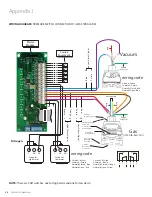
40
Amico Corporation
Appendix K
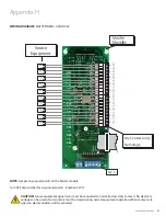
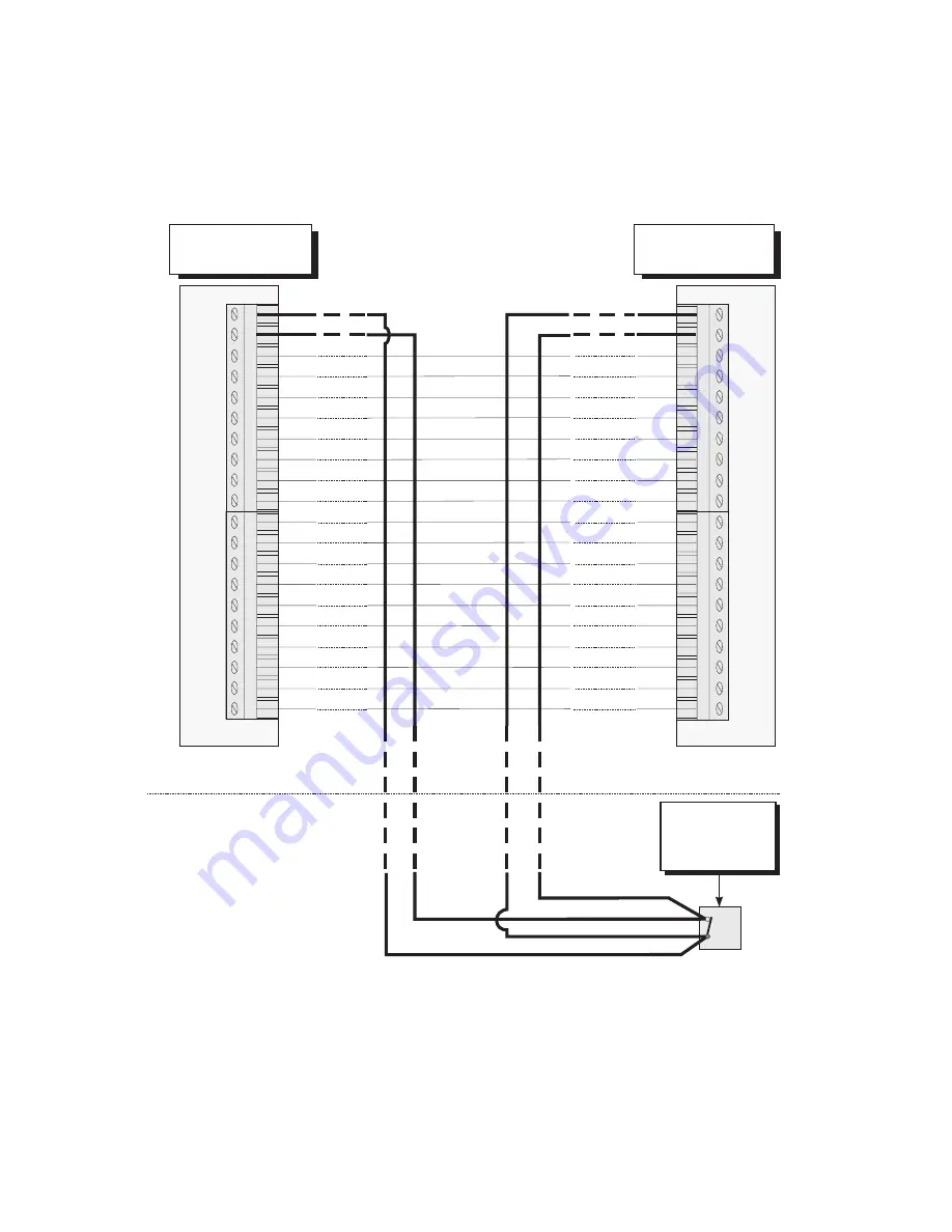
Wiring Diagram Master to Slave Module
"Master 1" "Master 2"
1
H
C
1
H
C
2
H
C
2
H
C
3
H
C
3
H
C
4
H
C
4
H
C
5
H
C
5
H
C
6
H
C
6
H
C
7
H
C
7
H
C
8
H
C
8
H
C
9
H
C
9
H
C
0 1
H
C
0 1
H
C
-
C
Source
Equipment
(typical)
Note: Turn OFF dip-switches for any unused points
(Location SW-2)
+
-
+
-
+
-
+
-
+
-
+
-
+
-
+
-
+
-
+
-
+
-
+
-
+
-
+
-
+
-
+
-
+
-
+
-
+
-
+
NC
NOTE:
Jumper any unused points on the Master module. Turn OFF dip-switches for any unused points (Location SW-2).
Each pair of terminals on the signal board connector is labeled “+” and “-”. Ensure that when a source equipment dry
contact is wired to two master panels, the same side of the dry contact is wired to two master panels. For example, if the
source equipment is normally closed, contact is wired to the “+” of the first master panel. Ensure it is also connected to
the “+” terminal of the second master panel.

