1
www.amico.com
User Responsibility
WARNING:
denotes steps which can prevent injury.
CAUTION:
denotes steps which can prevent damage to equipment.
DANGER:
denotes steps which can prevent electrical shock to
equipment or to prevent serious injury and/or death.
The information contained in this Installation and Operation Maintenance Manual, pertains only to the ALERT-2
microprocessor based digital alarm. This product will perform to conformity with the descriptions contained in this
manual, when assembled, operated, maintained and serviced in accordance with the installation instructions provided.
The alarm must be checked periodically. Parts that are broken, missing, worn, distorted or contaminated, must be
replaced immediately. Should such repair or replacement become necessary, please contact Amico Corporation or their
distributors.
All alarms should not be repaired, or altered without prior written or verbal approval of Amico Corporation or its distributors.
Failure to comply will void all warranty on the alarm.
Statements in this manual preceded by the words
WARNING, CAUTION, DANGER
and
NOTE
are of special significance.
Please read these sections carefully.
NOTE: Amico strongly recommends that alarms be checked annually by qualified staff.
Introduction
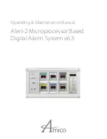
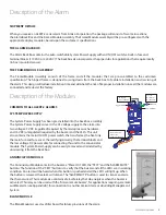
The AMICO Medical Gas Alarm System (ALERT-2) incorporates the latest microprocessor technology for alarm and
surveillance systems. The alarm has been designed to provide user flexibility and reliability. This manual will enable the
customer to install, use and maintain the alarm properly.
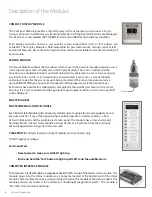
All Gases or Vacuum are displayed with large Red LED’s for clear visibility. To facilitate the monitoring function by hospital
personnel, a trend bar is provided to show the direction of the gas/vacuum pressure. Under normal operation, the gas
trend indicator will be in the GREEN - OK position. If the gas pressure approaches alarm condition, the trend indicator
will display a YELLOW - Caution indicator. If an alarm condition occurs, a RED-Alarm indicator will be displayed and the
buzzer will sound.
There are two buttons located on the front face of the Annunciator module. They are the “TEST” and “ALARM MUTE”
buttons. The function of the “Test” button is to verify that the buzzer and all the alarm LED’s are in normal working condition.
The function of the “Alarm Mute” button is to silence an alarm that has occurred.
A master status module monitors source equipment such as: Oxygen, Nitrous Oxide, Air compressors, Vacuum pumps,
Air dryers, high/low pressure switches, etc. This module can be connected to a “Building Management System”, with a
piggy-back computer interface board, that attaches to the master module.
The Alert-2 microprocessor based digital alarm system complies with NFPA 99 and UL Listed to U.S. and Canadian safety
standards.

