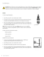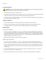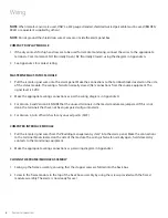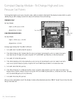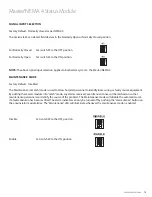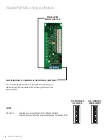
3
www.amico.com
Description of the Modules
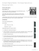
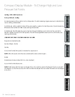
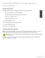
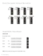
COMMON TO ALL ALERT-2 ALARMS
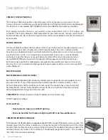
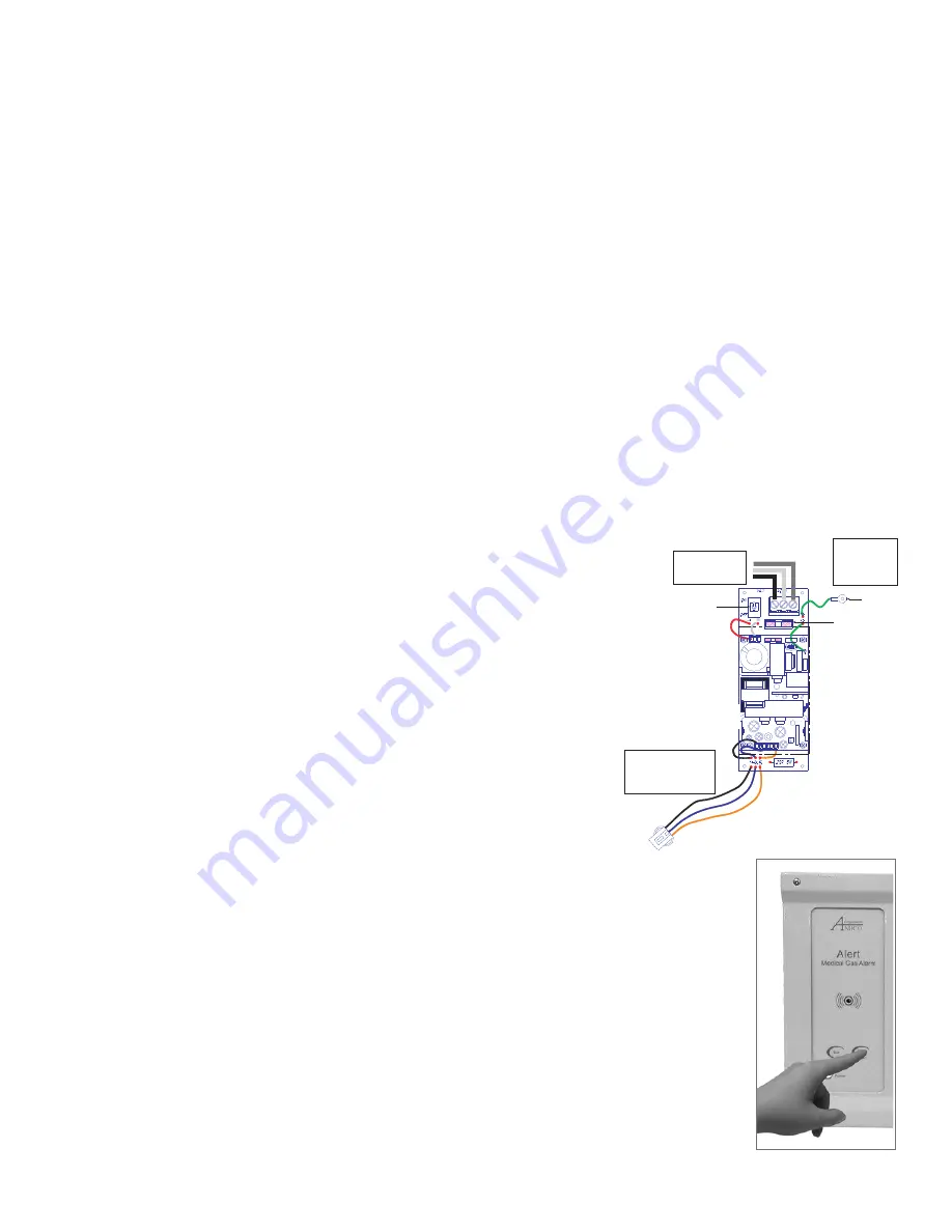
SYSTEM POWER SUPPLY
The System Power Supply has been pre-installed into the back box assembly.
The System Power Supply converts the AC voltage supply to the alarm into
two voltages: 5 VDC (regulated) required by the microprocessor hardware
and 15 VDC (unregulated) required by the buzzer and the LED’s. This unit
also contains the main ON/OFF power switch, the transformer, the heat sink,
the main fuse and fuse cover, the rectifying circuitry, the terminal blocks and
the low voltage DC power cable for connecting this unit to the annunciator
module. The System Power Supply can be easily removed and reinstalled by
unscrewing it from the back box.
ANNUNCIATOR MODULE
The Annunciator Module contains the buzzer, a “Power On” LED, the “TEST” and the “ALARM MUTE”
buttons. The function of the “TEST” button is to verify that the buzzer and all the LED’s are in working
condition. An alarm will be heard when this button is pushed and all the LED’s will light up. When
the button is released, the alarm will silence. The “ALARM MUTE” button is used to silence an alarm
that has occurred. This module also contains a fail-safe relay that de-energizes when the buzzer is
activated. This relay can be used with the “Amico remote buzzer”, for applications requiring a remote
audible alarm (see Appendix B), for connection to another Amico Alarm or a Building Management
System.
BLANK MODULE
The Blank Module is used as a filler board for future provisions of the alarm.
Description of the Alarm
A m i c o M i c r o p r o c e s s o r B a s e d A l a r m
P a g e : 8
DESCRIPTION OF MODULES
The ALERT-2 alarm is divided into (4) or (7) main modules:
COMMON TO ALL ALARMS
1. SYSTEM POWER SUPPLY
The System Power Supply has been pre-installed into the back box
assembly. The System Power Supply converts the AC voltage supply to
the alarm into two voltages: 5 VDC (regulated) required by the
microprocessor hardware and 15 VDC (unregulated) required by the
buzzer and the LED’s. This unit also contains the main ON/OFF power
switch, the transformer, the heat sink, the main fuse and fuse cover, the
rectifying circuitry, the terminal blocks and the low voltage DC power
cable for connecting this unit to the annunciator module. The System
Power Supply can be easily removed and reinstalled by unscrewing it
from the back box.
2. ANNUNCIATOR MODULE
The Annunciator Module contains the buzzer, a “Power On” LED, the
“TEST” and the “ALARM MUTE” buttons. The function of the “TEST”
button is to verify that the buzzer and all the LED’s are in working condi-
tion. An alarm will be heard when this button is pushed and all the LED’s
will light up. When the button is released, the alarm will silence. The
“ALARM MUTE” button is used to silence an alarm that has occurred. This
module also contains a fail-safe relay that de-energizes when the buzzer
is activated. This relay can be used with the “
Amico remote buzzer
”, for
applications requiring a remote audible alarm (see Appendix B), for
connection to an other Amico Alarm or a Building Management System.
3. BLANK MODULE
The Blank Module is used as a filler board for future provisions of the
alarm.
SHIPMENT DETAILS
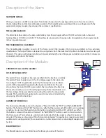
When you receive an ALERT-2 series alarm from Amico Corporation, the package will consist of two main sections;
the Alarm Back Box and the Frame/Module Assembly. The Frame/Module assembly will be pre-configured, with the
appropriate display modules, based upon the customer’s specifications.
THE ALARM BACK BOX
The Alarm Back Box contains the auto-switchable System Power Supply with an ON/OFF switch, a built-in fuse and
terminal blocks (115 VAC, or 220 VAC). The back box also incorporates the pipe stubs for applications that require locally
(in box) mounted sensors.
THE FRAME/MODULE ASSEMBLY
The Frame/Module Assembly consists of the frame and all the modules that are pre-assembled to the customers
specification. The hinged frame is designed to swing down from the back box to facilitate installation and servicing of
the alarm. This design will reduce installation time and eliminate the risk of improper installation since all the modules are
connected and tested at the factory.
AC Supply
115 to 220 VAC
DC Power Cable:
Connect to
Annunciator Module
G
N
L
L - Live
N - Neutral
G - Ground
Fuse (1 AMPw)
Ground
Toggle Switch
AC Supply
115 to 220 VAC
L = Live
N = Neutral
G = Ground
Ground
Fuse (1 AMPw)
Toggle Switch
DC Power Cable:
Connect to
Annuciator Module

