4
Amico Corporation
Description of the Modules
A m i c o M i c r o p r o c e s s o r B a s e d A l a r m
P a g e : 1 0
MASTER ALARM
7. MASTER/NEMA 4 STATUS MODULE
Each Master Status Module will continuously monitor up to 10 signals from
source equipment and pressure switches. If any of the signals being
monitored go into an alarm condition, a red LED will illuminate and the
audible alarm will sound. The module has a
slow
and a
rapid
flashing LED
rate. The last alarm condition always flashes at a
rapid
rate, while the
previously acknowledged alarms always flash at a
slow
rate.
PLEASE NOTE:
Contacts located on back of module are Dry Contacts
only. DO NOT apply any voltage.
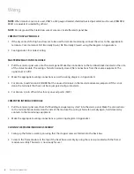
8. COMPUTER INTERFACE MODULE
The Computer Interface Module is a piggyback board that fits on top of the
master status module. This module plugs into the status module via a
connector, located at the bottom end of the status module. There are three
mounting screws provided to secure this module to the status module.
This module provides dry contacts
for interface to a “
Building Manage-
ment System
”. The module is “Fail-
Safe”, closed circuit monitoring.
NOTE:
The computer interface
module is not compatible with the 2
in 1 board.
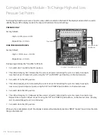
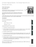
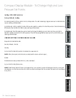
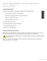
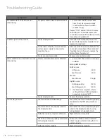
COMPACT DISPLAY MODULE
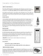
The Compact Module provides a digital display of the actual pressure/vacuum of a gas
being monitored. In addition a gas trend indicator bar with High and LOW alarms are displayed.
The trend bar as two colored LED’s: GREEN for Normal and RED for High and Low condition.
Each display module contains a gas specific colour coded label (USA or ISO colours are
available). The Display Module is field adjustable for pressure/vacuum settings, repeat alarm,
and unit of measure. Dry contacts for high and low alarms are available for remote monitoring of
each module.
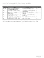
SENSOR MODULE
The Sensor Module contains the transducer which converts the pressure/vacuum pressure source
into a digital signal that is displayed on the Display Module. The sensor module shall be
housed in an anodized aluminum and nickel-plated brass enclosure to act as a barrier against
any interference and it is also temperature compensated. Each sensor is clearly labeled
and colour coded for the gas or vacuum being monitored. The sensor module contains a
gas specific DISS fitting to ensure correct connection of the proper sensor to the respective gas.
Each sensor has been factory calibrated by computer for the specific gas shown on the sensor
housing. If it is not connected to the appropriate gas display module, an error message (EO2)
will be displayed.
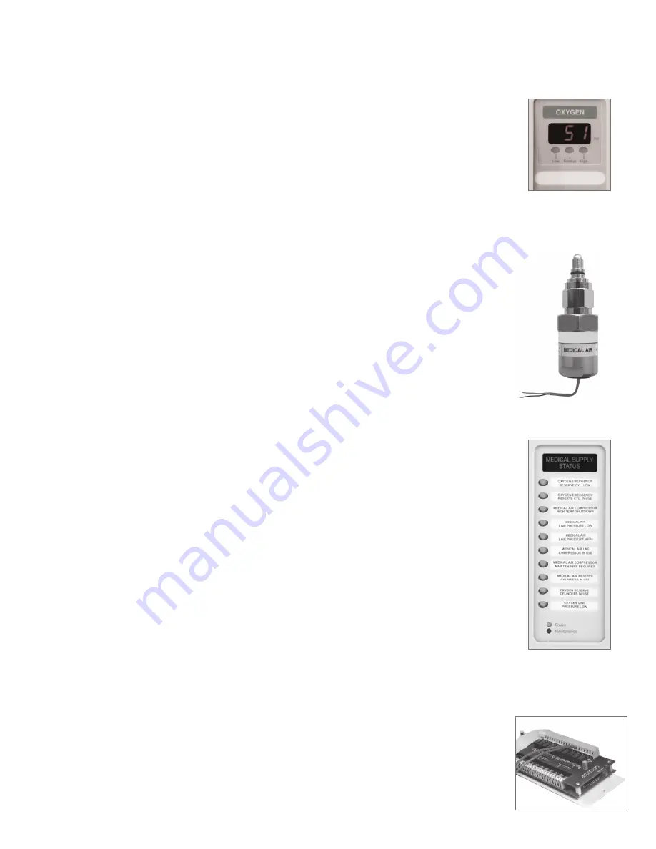
MASTER ALARM
MASTER/NEMA 4 STATUS MODULE
Each Master Status Module will continuously monitor up to 10 signals from source equipment and
pressure switches. If any of the signals being monitored go into an alarm condition, a Red
LED will illuminate and the audible alarm will sound. The module has a slow and a rapid
flashing LED rate. The last alarm condition always flashes at a rapid rate, while the previously
acknowledged alarms always flash at a slow rate.
PLEASE NOTE
: Contacts located on back of module are Dry Contacts only.
DO NOT apply any voltage.
For Annual Test
• Reset power to make sure all LED’s light up
• Push and hold the ‘Test’ button to light up all LED’s and the audible alarm
COMPUTER INTERFACE MODULE
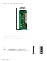
The Computer Interface Module is a piggyback board that fits on top of the master status module. This
module plugs into the status module via a connector, located at the bottom end of the status
module. There are three mounting screws provided to secure this module to the status module. This
module provides dry contacts for interface to a “Building Management System”. The module is
“Fail-Safe”, closed circuit monitoring.

