www.amico.com
9
STEP 6: SYSTEM POWER SUPPLY
CAUTION:
TURN OFF POWER SWITCH BEFORE CHANGING ANY MODULES AND/OR DISCONNECTING ANY CABLES.
FAILURE TO DO SO CAN CAUSE THE FUSE TO BLOW, DAMAGING THE CIRCUITRY.
i. Ensure that the ON/OFF switch is in the OFF position.
ii. Through the top left side of the back box, bring in the AC power wires. Knockouts are provided for making
conduit connections to the box. All wiring is to be installed according to local and national codes.
iii. Connect the AC power to the terminal blocks as shown in the wiring diagram (see Appendix B).
CAUTION:
1. Verify that power has been switched off prior to working on the alarm
2. Risk of electric shock. Disconnect power at the circuit breaker before removing power supply shield
STEP 7: SENSOR MODULE
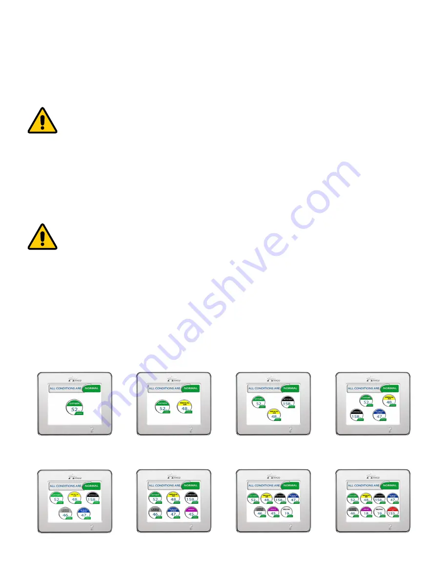
A: GAS DISPLAY (on screen location)
The location of gases displayed on screen is dependant upon which sensor channel each individual gas is connected
to. The display below indicates which sensor channel corresponds to each location the gas will be displayed on the LCD
screen.
1
1
2
1
2
3
1
2
3
4
1
2
3
4
5
1
2
3
4
5
6
1
2 3 4
5
6
7
1 2
3 4
5 6
7 8
Installation Guide


