27
www.amico.com
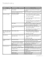
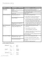
Troubleshooting
Symptom
Cause
Corrective Action
An error or “LOW ALARM”
LCD screen
The Microprocessor detected a fault and
has shut down
Turn power switch to OFF position. Wait for at least 5
seconds before turning ON the power. The program will
reset itself.
Faulty wire connection between the
sensor and LCD module
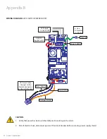
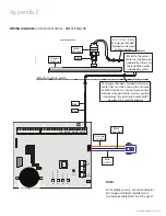
Check wiring diagram in Appendix D and Appendix E
No power on the alarm
AC power not available
a. Ensure that the ON/OFF switch on the power
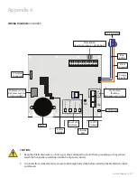
supply module is turned ON (see Appendix B).
b. AC wiring not connected.
c. Check the building electrical breaker to ensure
that the power is ON.
d. Check the voltage at the terminal block above the
transformer. Ensure that 115 VAC to 220 VAC is
being supplied.
Fuse is blown
Check the fuse. The fuse is located on the upper-right
corner of the system power supply. Replace the fuse if it
is defective (see Appendix B and Appendix G).
DC power plug not connected to the LCD
module
a. Ensure that the DC power plug is firmly in its
socket on the LCD module.
b. Replace the System Power Supply unit if all the
above steps fail to resolve the problem.
Power light is ON, however
there is no display on LCD
screen
Power failure on screen
a. Remove all transducers and reset power by
switching the power supply OFF, then ON.
b. Replace the LCD module.
No audible alarm
DC power cable is disconnected or loose,
check ribbon cable
a. Ensure that the DC power cable from the system
power supply is firmly connected to the LCD
module.
b. Replace LCD module.
Audible signal will not
silence
Faulty display module
Disconnect the ribbon cable from the back of the faulty
display module and replace the LCD module.
Connection of the DC power cable from
system power supply to LCD module is
loose
Disconnect the DC power cable from the LCD module
and then reconnect. If audible alarm still persists,
replace the System Power Supply unit.
Faulty push button
Replace the LCD module.
Gas reading incorrect
Loose connection of DISS fittings
Ensure that the sensor module is properly connected to
the DISS demand check-valve
Sensor module is not properly wired to
the display module
Ensure that the sensor module is properly wired to the
LCD module by using wiring diagram in Appendix D or
Appendix E
Requires calibration
Re-calibrate pressure reading (see page 11, Step 9 - iv,
“CURRENT OFF SET”)
Defective sensor
Replace the sensor module
Defective LCD display
Replace the LCD module

