33
www.amico.com
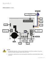
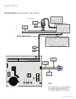
WIRING DIAGRAM:
LCD DISPLAY MODULE - REMOTE SENSOR
Note:
For multiple sensors, a
multi-conductor twisted
pair cable can be used.
OXYGEN
# 22 Gauge twisted
pair shielded cable
6”-8” [0.1m-0.2m] supplied
Junction Box
(by others)
Sensor
Module
DISS
Oxygen
Pipeline
Remote location alarm
AC Supply
115 to 220 V
AC
DC P
ower Cable
:
Connect to
Annunciator Module
G
N
L
L - Live
N - Neutral
G - Ground
Fuse (1 AMPw)
Gr
ound
To
ggle S
wit
ch
COM
B4
et
u
M /
tc
el
e
S
N
W
O
D
eg
na
h
C
P
U
eg
na
h
C
p
U -
te
S
B3
B2
B1
+12V
NO
NC
GRND
Reset
Button
S 8
S 7
S 6
S 5
S 4
S 3
S 2
S 1
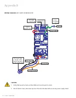
NOTE:
For multiple sensors, a multi-conductor
#22 Gauge stranded, shielded and
twisted pair cable ONLY must be used.
Appendix E
Sensor
Module
Oxygen
Pipeline
DISS
6" - 8" [0.1m - 0.2 m]
#22 gauge stranded,
shielded twisted pair
cable supplied
Marrette the sensor
cable in a junction box
(supplied by others) to
the installation cable
(supplied by others)
#22 gauge stranded, shielded twisted pair
cable ONLY must be used, up to a distance
of 2000 ft [609.6 m]. In the presence of any
electrical, magnetic radio, wireless or other
interference, the installation cable MUST
be placed in a metallic conduit
Red
Black
Orange
(15 VDC)
Blue
(5 VDC)
Black
(Ground)


