background image

    35

www.amico.com

1.  General Requirements

1.  All wiring shall be protected from physical damage by raceways, cable trays or conduit in accordance with NFPA 

70, National Electric Code or the Canadian Electrical Code.

2.  All alarms are to be powered from the life safety branch of the emergency power system as required by 

applicable standards.

3.  Alarm panel wires should be directly connected to switches or sensor as required by applicable standards.

4.  All wire runs should be made with color coded wire. Record color, signal and source of signal for each wire lead 

to aid in connection of alarm finish components.

5.  The alarm panel and remote sensors should not be installed near radio transmitters, electrical motors, electrical 

control room, switch gear, CT scanners, MRI machines or high voltage lines

6.  In the presence of any electrical, magnetic, radio frequencies, wireless or other interference, cable installation 

MUST be placed in metallic conduits.

7.  No solid wire should be used for connecting sensors or master alarms to source equipment

8.  To protect from static electricity, ensure to discharge body static before installing the Medical Gas Alarm and 

Sensors

9.  Do not ground the shield drain wire at sensor or inside alarm panel back box

2.  Low Voltage wire type, size and other requirements

All low voltage wiring must meet the following criteria:

1.  #22 AWG stranded, shielded twisted pair wire ONLY must be used, rated for 300V and 60°C (140°F) minimum. 

(Belden 8451 or equivalent)

2.  Marrette the sensor cable in a junction box (supplied by others) to the installation cable (supplied by others) 

to protect from physical damage, radio frequencies and EMI

3.  For multiple sensors, a multi-conductor #22 gauge stranded, shielded and twisted pair cable ONLY must be 

used

The following rules along with references to this manual’s schematics clarify wiring requirements. Two conductor cables 

(must be #22 gauge stranded, shielded and twisted pair cable type) are required for each Gas Sensor module to the Gas 

Input board.

Appendix G

WIRING

Summary of Contents for Alert-4

Page 1: ...Operating Maintenance Manual Alert 4 LCD Ethernet Area Alarm...

Page 2: ...arm Box 7 For Local Sensors Only 7 Standing Pressure Test 7 Sensor 7 8 Local 7 Remote 8 Frame Assembly 8 9 System Power Supply 9 Sensor Module 10 Gas Display 10 Local 10 Remote 10 LCD Display Module 1...

Page 3: ...Dimensions 26 LCD Alarm 26 Alert 4 Sensor 26 Troubleshooting 27 28 Appendix A 29 Wiring Diagram LCD Board Appendix B 30 Wiring Diagram Auto Switch Power Supply Appendix C 31 Wiring Diagram LCD Displa...

Page 4: ...n or its distributors Failure to comply will void all warranty on the alarm Statements in this manual preceded by the words WARNING CAUTION DANGER and NOTE are of special significance Please read thes...

Page 5: ...tton Microprocessor based digital LCD and individual microprocessor on each sensor module Ethernet capable for viewing an exact image of the alarm remotely or wireless anywhere in the building Gas spe...

Page 6: ...his module also contains a fail safe relay that de energizes when the buzzer is activated This relay can be used with the Amico Remote Buzzer for applications requiring a remote audible alarm master a...

Page 7: ...STEP 2 FOR LOCAL SENSORS ONLY If the sensors are to be mounted locally inside the back box the pipe stubs must be connected to the pipeline Using silver brazing techniques connect each pipe stub to it...

Page 8: ...lied by others to the alarm MUST be placed in a metallic conduit Installation Guide P a g e 1 2 2 In the back box there are colour coded gas labels located under the DISS Demand check valves Each labe...

Page 9: ...anging any modules and or disconnecting any cables Failure to do so can cause the fuse to blow damaging the circuitry 1 Ensure that the ON OFF switch is in the OFF position 2 Through the top left side...

Page 10: ...Repeat the above procedures with the remaining sensor modules C REMOTE outside the back box i The sensor module is provided with 6 8 0 1m 0 2m 22 gauge stranded shielded and twisted pair cable Connect...

Page 11: ...display the gas type automatically Example OXYGEN vii Select unit of measure Gas PSl BAR KPA for Vacuum in HG mmHg press CHANGE UP B2 DOWN B3 to change press CHANGE UP B2 DOWN B3 to change and B4 to s...

Page 12: ...alarm to PC using cat 5 Ethernet cable NOTE It is best to use a switch instead of a hub because the device communicates at 10 Mbps A switch is better able to support this speed improves network perfo...

Page 13: ...med network to change the network IP address Change the default IP address to the desired IP address Gateway and Subnet Mask then save the file by clicking File then Save When all files are saved in t...

Page 14: ...eps above If the problem persists contact Amico Corporation for further assistance Once the information is visible on the LCD Alarm screen leave the SD Card in the slot for approximately 1 minute in o...

Page 15: ...SMTP_PASSWORD provide SMTP password EMAIL provide recipient email address DEVICE_ID location where device is installed To load the Network configuration press and hold the Reset and Setup buttons at...

Page 16: ...vide SMTP user name SMTP_PASSWORD provide SMTP password EMAIL provide recipient phone number and SMS gateway address e g phonenumber txt bell ca DEVICE_ID location where device is installed To load th...

Page 17: ...le Chrome Internet Explorer Enter the device IP address eg http 192 168 1 1xx in the browser s address bar NOTE To find Alarm IP Address press reset button on the back of the Alert 4 Area Alarm SIMPLE...

Page 18: ...e SD card in the SD card slot to record the logs Panel will automatically log the track of alerts with date and time provided 1 To view the logs 2 Remove the SD card from the SD card slot 3 Plug the S...

Page 19: ...matically To Mute the audio click the mute button on the web page If the PC audio doesn t turn on automatically click mute and re activate the alert to turn PC Audio ON Note By muting the audio in the...

Page 20: ...pendix A 6 While the LCD Alarm is on to load gas location location txt file press and hold the Reset and Setup buttons at the same time for two seconds Let go of the Reset button while still holding t...

Page 21: ...he event of a gas outage The App will also help maintenance personnel to localize the outage for a quicker resolution NOTE If Alert 4 alarm is given with local IP address the phone must be connected t...

Page 22: ...ile Eco System App Press and hold the device screen to move the device Device Manual Display Exact Image of the Alarm Click to Open Manuals Click to Contact Amico Slide Left to Delete Device Click to...

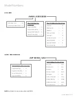
Page 23: ...e L Defines the Language English NFPA U English CSA ISO E French CSA ISO F Spanish NFPA S Remote Local R Conversion Retrofit C The X Defines theType of Gas Oxygen O Medical Air A MedVac V Nitrous Oxid...

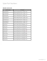
Page 24: ...A3P SENS U IAR Sensor Module USA IAR Eng Alert 3 Model Number Description A2P POWER V2 Power Supply Module Alert 2 A2P BOXASS 3LCD Alarm Back Box Assembly 3 Station Alert 2 A2X BOX ASY 3LCD Alert 3 LC...

Page 25: ...k Valve 1 4 MNPT OXY S DIS DEMC VAC DISS Demand Check Valve 1 4 MNPT VAC S DIS KIT OXY DISS Demand Check Nut and Nipple OXY S DIS KIT AIR DISS Demand Check Nut and Nipple AIR S DIS KIT VAC DISS Demand...

Page 26: ...M THD Brass 1 25 HEX 1 4 6 NPT 71 2 191 6 3 8 162 NOTE DISS demand check valves by 1 4 6 NPT supplied with each sensor Brazing Filler Metal AWS Spec BAg 7 Approximate can vary 1 2 Conduit Connection 7...

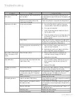
Page 27: ...em Power light is ON however there is no display on LCD screen Power failure on screen a Remove all transducers and reset power by switching the power supply OFF then ON b Replace the LCD module No au...

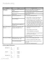
Page 28: ...ddress of the panel then hit Enter When panel is responded with a ping connection is successful Dynamic IP address Wrong port number assigned to the network switch Email or Text notification not send...

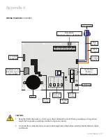
Page 29: ...GRAM LCD BOARD CAUTION 1 Keep the shield drain wires as short as possible and taped to prevent from grounding so they cannot touch the front panel circuit board when front panel is closed 2 To protect...

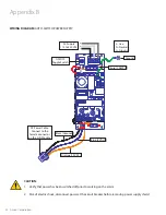
Page 30: ...nd Toggle Switch CAUTION 1 Verify that power has been switched off prior to working on the alarm 2 Risk of electric shock disconnect power at the circuit breaker before removing power supply shield Or...

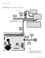
Page 31: ...U t e S B3 B2 B1 12V NO NC GRND Reset Button S 8 S 7 S 6 S 5 S 4 S 3 S 2 S 1 NOTE Relays on the annunciator are fail safe for Version 3 1 or newer NC COM NO 12V GND NO COM NC 12V GND Optional To Amic...

Page 32: ...Reset Button S 8 S 7 S 6 S 5 S 4 S 3 S 2 S 1 OXYGEN 22 Gauge twisted pair shielded cable 6 8 0 1m 0 2m supplied CAUTION To protect from static electricity ensure to discharge body static before instal...

Page 33: ...t Button S 8 S 7 S 6 S 5 S 4 S 3 S 2 S 1 NOTE For multiple sensors a multi conductor 22 Gauge stranded shielded and twisted pair cable ONLY must be used Appendix E Sensor Module Oxygen Pipeline DISS 6...

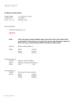
Page 34: ...equivalent In the presence of any electrical magnetic radio frequencies wireless or other interference cable installation MUST be placed in metallic conduit Distance Maximum 2000 ft 609 6 m Signal 30...

Page 35: ...MUST be placed in metallic conduits 7 No solid wire should be used for connecting sensors or master alarms to source equipment 8 To protect from static electricity ensure to discharge body static befo...

Page 36: ...4 LCD AREA ALRM 09 24 2019 Amico Corporation 85 Fulton Way Richmond Hill ON L4B 2N4 Canada 71 East Industry Court Deer Park NY 11729 USA Toll Free Tel 1 877 462 6426 Tel 905 764 0800 Fax 905 764 0862...

Reviews: