8 Amico Corporation
Alert-3 sensor operating pressure range:
Mid Pressure
(0 to 99 psi)
-
Oxygen, Medical Air, Nitrous Oxide, Carbon Dioxide
High Pressure
(0 to 249 psi)
-
Nitrogen, Instrument Air
Vacuum
(0 to 30 inHg)
-
Vacuum, WAGD, AGSS
CAUTION:
To protect from static electricity, ensure to discharge body static before installing the Medical Gas
alarm and sensors. Do not ground the sheild drain wire at sensor or inside alarm panel back box.
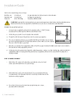
B: REMOTE (outside the back box)
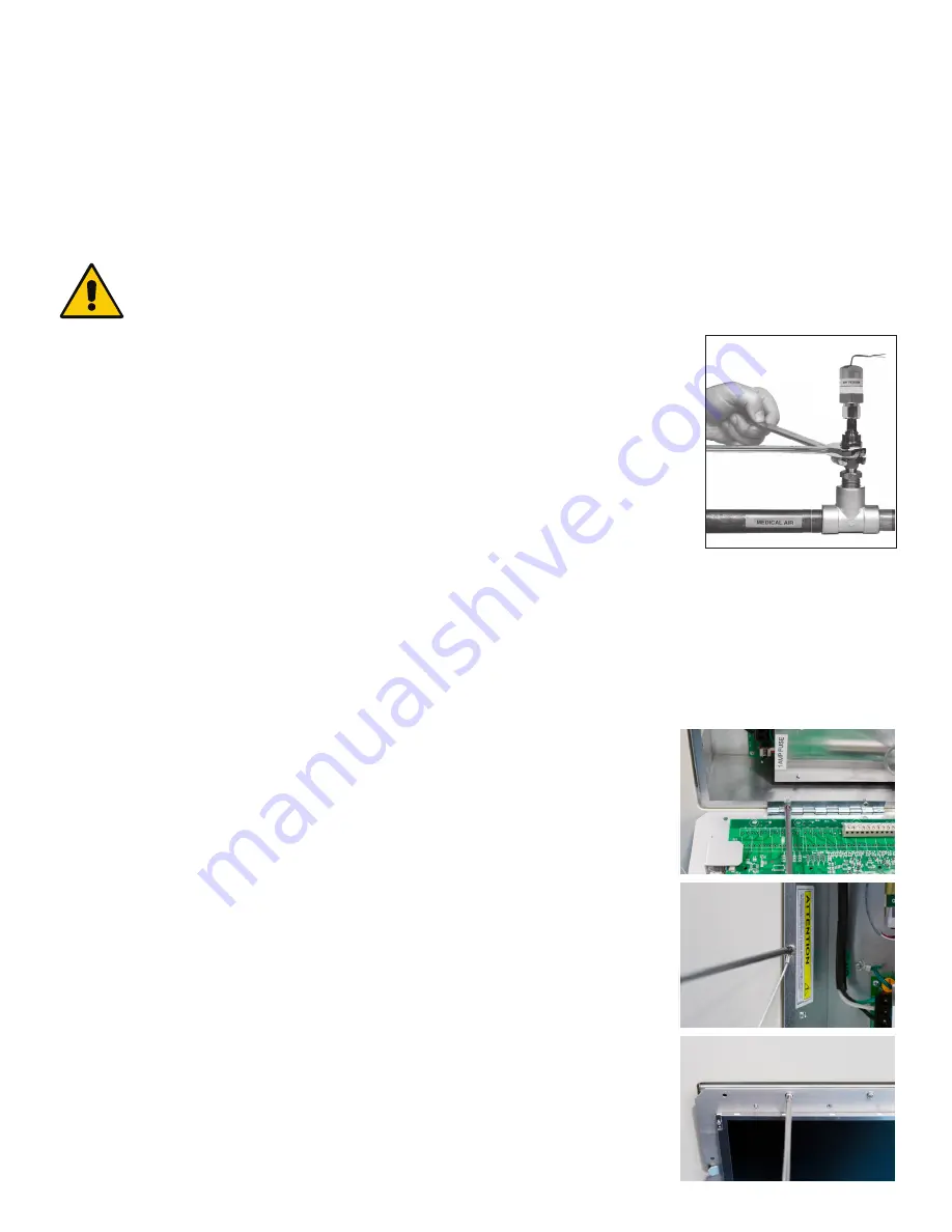
i. Connect a tee (supplied by others) to the pipeline with a 1/4" NPT female
connection that will accept the DISS Demand Check Valve.
ii. Locate the gas-specific sensor module to be installed.
iii. Thread the DISS Demand Check Valve into the correct gas pipeline.
iv. The sensor module contains a gas-specific DISS fitting. Push the sensor module
hex-nut and nipple adapter into the demand check-valve. With a wrench, tighten
the nut so that it makes a good seal.
v. Marrette in a junction box (supplied by others) the #22 gauge stranded, shielded twisted pair sensor cable to
the installation cable (supplied by others).
vi. In the presence of any electrical, magnetic, radio frequencies, wireless or other interference, cable installation
(supplied by others) running from the junction box (supplied by others) to the alarm MUST be placed in a
metallic conduit.
Installation Guide
A m i c o M i c r o p r o c e s s o r B a s e d A l a r m
P a g e : 1 2
CAUTION:
The microprocessor circuitry on the ALERT-2 alarm con-
tains sophisticated integrated semiconductors. If it becomes necessary
to remove a module, PLEASE hold the boards by the edges.
DO NOT
TOUCH
any of the components on the board. Static discharge can
cause the modules to malfunction, or become damaged.
SENSOR
LOCAL (In the Back Box)
1.
Locate the gas specific
sensor module to be in-
stalled.
2.
In the back box, there are
colour coded gas labels
located under the DISS
Demand check valves. Each
label identifies where each
sensor module is to be
placed.
3.
The sensor module contains
a gas specific DISS fitting.
Push the sensor module
hex-nut and nipple adapter
up into the demand check-
valve. With a wrench, tighten the nut so that it makes a good seal.
NOTE: Pressure on sensors are not to exceed
250psi
for Pressure sensors and
30”
for Vacuum sensors
REMOTE (Outside the Back Box)
1.
Connect a Tee (supplied
by others) to the pipeline
with a 1/4" NPT female
connection that will accept
the DISS Demand check-
valve.
2.
Locate the gas specific
sensor module to be
installed.
3.
Thread the DISS Demand
check-valve into the
correct gas pipe line.
4.
The sensor module contains a gas specific DISS fitting. Push the
sensor module hex-nut and nipple adapter up into the demand
check-valve. With a wrench, tighten the nut so that it makes a
good seal.
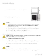
i. Attach the LCD screen to the back box assembly by using star head
screws (provided with frame in a plastic bag).
STEP 5: FRAME ASSEMBLY
ii. Attach the frame wire with 2 dome head screws (provided with frame
in a plastic bag). This will allow the frame assembly and back box to the
fastened securely together.
iii. Close the LCD screen with a back box by tightening two screws
provided with divider plate.


