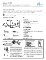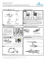
Falcon IT (FIT)
Quick Installation and Adjustment Instructions
Amico Accessories Inc. | 85 Fulton Way, Richmond Hill, ON L4B 2N4, Canada | www.amico.com
Toll Free Tel: 1.877.264.2697 | Tel: 905.763.7778 | Fax: 905.763.8587 | Email: info@amico-accessories.com
2
3. Rotation (AHM Side-to-side)
4. Head Tilt and Rotation
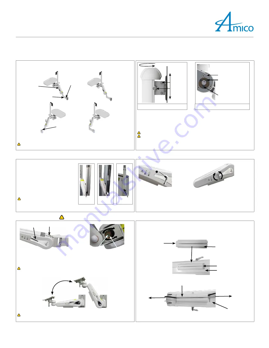
SECOND ARM ROTATED
TO ROTATE AHM ARM:
ROTATE MID POINT
AHM ARM
EXTENSION ARM
BOLT
AT
EXTENSION ARM
EXTENSION ARM ROTATED
TO ROTATE AT FIRST ARM
ROTATE END POINT
BOLT
AT EXTENSION
!
WARNING:
In
AHM ARM(
s) with extensions, both armsw have a 180
°
rotation. Ensure proper clearance
around the arm(s) to avoid collision (if applicable).
The monitor can swivel 360° (clockwise/counter-clockwise, left/right), it can also tilt up/down by +/- 15°.
Adjusting Tilt Tension:
Tighten or loosen the
LARGE SCREW
on the
MOUNTING BRACKET
and then
tighten or loosen the 2x
SMALL SCREWS
to fine tune the tension.
(Figure 1)
Adjusting Swivel Tension
: Slightly (one turn) loosen/tighten the
COUNTER-BALANCE BOLT
at the base
of the
KEYBOARD TRAY
, to adjust the rotational tension of both the monitor and the
KEYBOARD TRAY
,
slightly loosen/tighten the 3x
PHILLIPS HEAD SCREWS
at the base of the
KEYBOARD TRAY
.
(Figure 2)
!
WARNING:
Be sure to support the monitor if adjusting the tilt angle with the monitor mounted.
!
WARNING:
After the monitor is installed, tighten large and small tilt adjustment
SCREWS
to the
tightest position possible with the weight of the monitor attached. Alternate between tightening
LARGE SCREWS
and
SMALL SCREWS
until the appropriate tension is reached.
± 15°
SMALL
SCREWS
LARGE
SCREW
± 360°
Figure 1
KEYBOARD BASE
SCREWS
FOR ADJUSTING
TENSION OF BOTH
KEYBOARD TRAY
AND
SWIVEL BLOCK
SCREWS
FOR ADJUSTING
TENSION OF
SWIVEL
BLOCK
ONLY
Figure 2
5. FIT Post Cable Management
6. Height Locking Lever Adjustments
1. There are 2x
FIT CABLE GUIDE CHANNELS
in the
SWIVEL POST
, which is covered by the
SWIVEL
POST CABLE COVER
.
2. Pop out the
SWIVEL POST CABLE COVER
, take
your power cable for your all-in-one and place
the cable gently into the
GUIDE CHANNELS
towards your
AHM ARM
(Figures 1 & 2)
. Take
your cables from the keyboard tray and place
the cables into the
GUIDE CHANNELS
towards
your all-in-one.
!
WARNING:
Do not bunch cables together in
one
CABLE GUIDE CHANNEL
. Use separate
CHANNELS
for each cable.
CABLE GUIDE
CHANNEL
CABLE LAID
SWIVEL POST
CABLE COVER
Figure 1
Figure 2
Figure 3
To adjust the
AHM ARM
height, always be sure to loosen the
HEIGHT LOCKING LEVER
first.
INSERT
HEIGHT LOCKING LEVER
HEIGHT LOCKING LEVER
:
ROTATE COUNTER-CLOCKWISE
TO RELEASE, ROTATE CLOCKWISE TO LOCK.
7. Counter Balance
!
8. Cable Management
Loosening or tightening the
COUNTER-BALANCE
BOLT
will adjust the resistance of the arm.
When properly counter-balanced, the arm should
remain in neutral position when unlocked.
OPENING TO THE
COVER
HEIGHT LOCKING LEVER
COUNTER-BALANCE BOLT
(1/2")
COUNTER-BALANCE BOLT
(1/2”)
!
WARNING:
Do not over rotate the
COUNTER-BALANCE BOLT
. Once you feel resistance, stop counter-balancing.
Forcing the
COUNTER-BALANCE BOLT
will damage the internals of the
AHM ARM
and void the warranty.
!
WARNING:
KICK-BACK
motion: when the
AHM ARM
is locked and not in the highest position, it is capable of
rapidly lifting to the highest position once the
HEIGHT LOCKING LEVER
is released.
RA
PI
D
LIF
TIN
G (
KICK-
BACK
)
Insert cables into
CABLE GUIDE
, then squeeze
CABLE GUIDE
and press onto the bottom of the
AHM ARM
.
CABLE GUIDE
BOTTOM SIDE OF THE
AHM ARM
CABLE COVER
CABLE GUIDE
CABLE GUIDE
BOTTOM SIDE OF THE
AHM ARM
GROOVES
BOTTOM SIDE OF
CABLE COVER
TO ROTATE AT SECOND ARM
AA-QG-WALL-MOUNTED-COMPUTER-WORKSTATION-FALCON 07.25.2012


