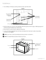
www.amico.com
3
Preparation Before Installation
1. Review a copy of the final approved shop drawing(s) and/or submittal package. These documents will provide you
with technical information specific to your installation, such as:
• Equipment types and quantities
• Room numbers and locations
• Shop drawings of each unit type
• Wiring diagrams and rough-in locations
2. Prepare the tools and hardware needed to complete the installation. Some common tools that may be required are:
• Cordless drill/driver with common drill or drive bits
• Hand tools (screwdrivers, 5/16" wrenches, clamps, pliers, etc.)
• Laser- or Bubble-level
• Ladder(s)
3. Locate the Artwall unit from the shipping boxes. The contents of each shipping box are listed on the shipping
document(s).
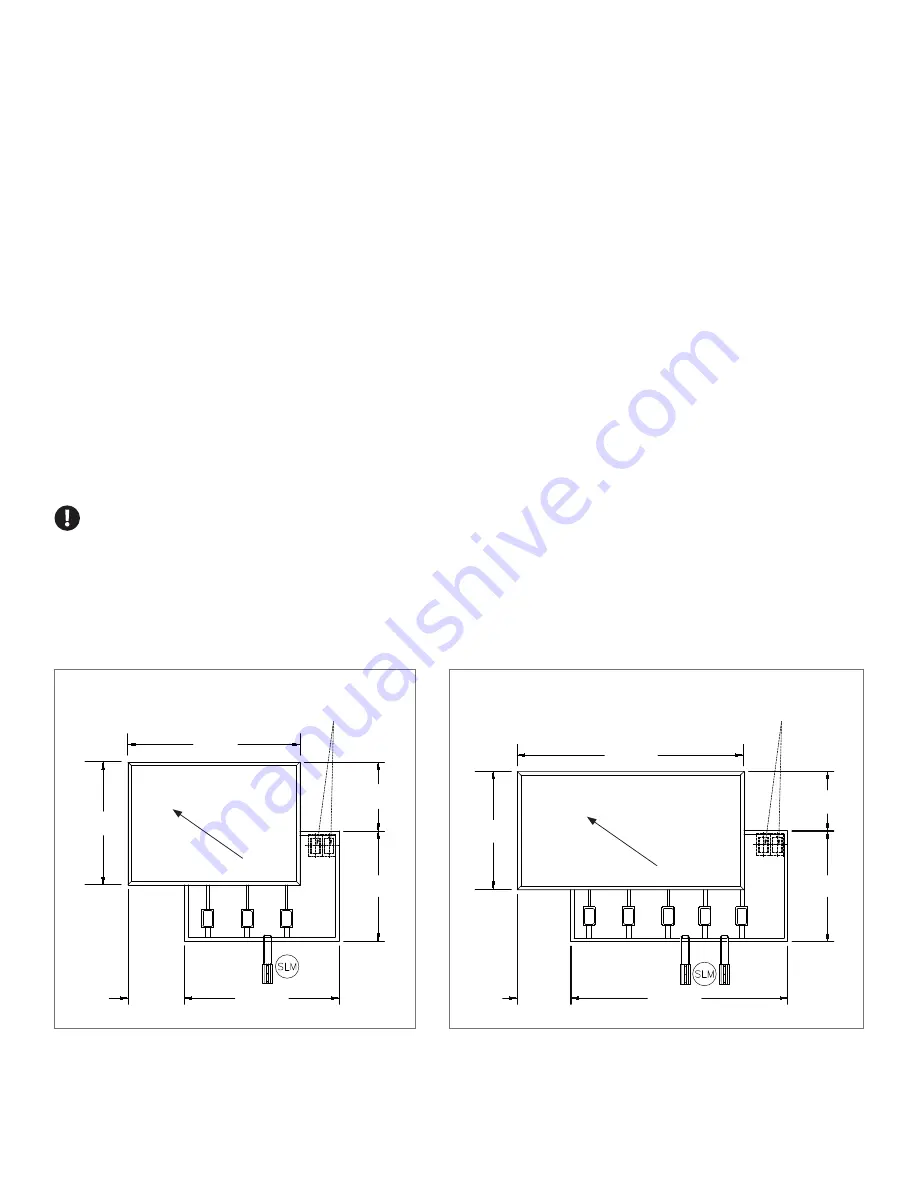
IMPORTANT:
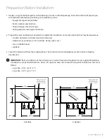
Before installation of the Artwall, ensure wall is framed and roughed in as per applicable building
standards to accept Artwall back box. Allow 1/8” space on each side to allow for adjustment. Back box sizes are as
follows:
• 3-gas box – 30 1/8" w x 21 1/8" h
• 5-gas box – 42 5/8" w x 21 1/8" h
O
V
A
V
A
O
O
V
3-Gas Box
14"
[356 mm]
35"
[889 mm]
25"
[635 mm]
22 1/2"
[572 mm]
31 1/2"
[800 mm]
11 1/2"
[292 mm]
Diagonal M
ovemen
t
Request for Electrical
Devices are to be
located at only these
2 positions as shown
O
V
A
V
A
O
O
V
5-Gas Box
12"
[305 mm]
46"
[1168 mm]
24"
[610 mm]
22 1/2"
[572 mm]
44"
[1118 mm]
Diagonal M
ovemen
t
10 7/8"
[275 mm]
Request for Electrical
Devices are to be
located at only these
2 positions as shown

