background image

     www.amico.com     

9

Section 3: Installation

Installation to HORIZONTAL RAIL SYSTEM (ARS) (-AT) 

Double Rail 

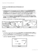
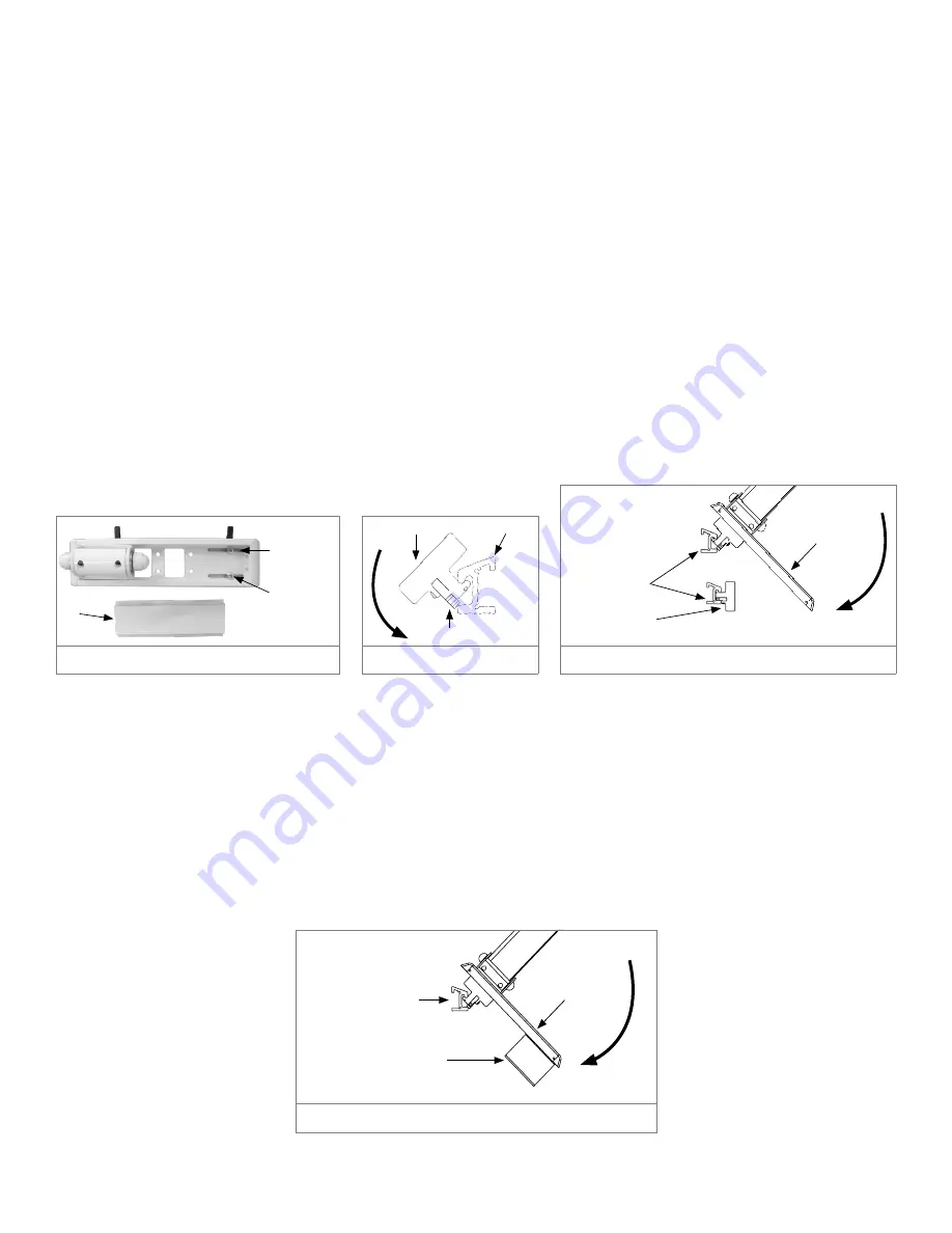
1.  If mounting to a headwall, determine the best location for installation and remove the 

MOUNTING ADAPTER 

CHANNEL COVER

 to access the 

2x SCREWS

 connecting the 

CHANNEL

 to the 

BOTTOM ARS ADAPTER

. Remove 

the 

2x SCREWS

 to free the 

BOTTOM ARS ADAPTERS

 (

Figure 7

). Install this 

BOTTOM ARS ADAPTER

 into the 

BOTTOM RAIL

 by angling the upper lip into the inside lip of the 

BOTTOM


ARS RAIL

, pull the 

LEVER

 back against 

the 

ARS ADAPTER

 and push the 

ADAPTER

 into the 

RAIL

. Once secure, release the 

LEVER.

 (

Figure 8

)

2.  Mount the Infusion Arm by installing the remaining 

ARS ADAPTER

 onto the 

TOP


ARS RAIL

 in the same way as 

step 1, ensuring the 

2X HOLES

 on the 

BOTTOM


ARS ADAPTER 

can be seen through the 

MOUNTING ADAPTER 

CHANNEL

, secure the 

MOUNTING ADAPTER CHANNE

l to the 

BOTTOM


ARS ADAPTER

 using 

SCREWS

 and 

LOCK 

WASHERS

 you removed in step 1. (

Figure 9

)

3.  Replace the 

CHANNEL COVER

 onto the 

MOUNTING ADAPTER CHANNEL

.

Single Rail 

1.  If mounting to a single rail, angle the upper lip of the 

ARS ADAPTER

 of the 

MOUNTING ADAPTER CHANNEL

 into 

the inside lip of the 

RAIL

, hold the tab on the 

ARS ADAPTER

 and push into the 

RAIL

. Once secure, release the tab 

and ensure the 

SUPPORT BLOCK

 is sitting flush and firmly against the wall. (

Figure 10

)

2.  Install the locking bar by placing it on top of the 

ARS ADAPTER

 of the 

MOUNTING ADAPTER CHANNEL

 so it is 

squeezed by the 

ADAPTER 

and

 ARS RAIL

.

SCREW, LOCK 

WASHERS

COVER

MOUNTING 

ADAPTER 

CHANNEL

Figure 7

MOUNTING 

ADAPTER CHANNEL

ARS RAIL

SUPPORT BLOCK

MOUNTING ON A  

SINGLE ARS

Figure 10

MOUNTING 

ADAPTER CHANNEL

ARS ADAPTER 

INSTALLED

ARS

RAIL

MOUNTING ON A 

HEADWALL

Figure 9

ARS ADAPTER

LEVER ON ARS

ARS RAIL

Figure 8

Summary of Contents for Roll Stand INE-0909-12-12-F4-M

Page 1: ...Installation Instructions Infusion Extension Arm...

Page 2: ...may be a direct or indirect result of failure to comply with the instructions provided in this manual Please Note these Key Words and Symbols WARNING Steps where extra care should be taken to prevent...

Page 3: ...ting Platform 8 Mounting to Monitor Rail System MRS M 8 Installation to Horizontal Rail System ARS AT 9 Double Rail 9 Single Rail 9 Mounting to Amico Vertical Rail System V 10 Section 4 Device Install...

Page 4: ...3 4 PRIVATE AND CONFIDENTIAL THIS PRINT IS PROPERTY OF AMICO ACCESSORIES AND IS LOANED IN CONFIDENCE SUBJECT TO RETURN UPON REQUEST AND WITH THE UNDERSTANDING THAT NO COPIES ARE TO BE MADE WITHOUT THE...

Page 5: ...ns Product Classifications INE XXXX 12 12 YY Z V AMICO VERTICAL RAIL ADAPTER M MRS RAIL ADAPTER AT AMICO HORIZONTAL RAIL ADAPTER 00 NO HOOK F4 FIXED 4 HOOK 0900 SINGLE EXTENSION 0909 DUAL EXTENSION DO...

Page 6: ...MBER PART DESCRIPTION H MPF 1032 12 Screws 4x HOOKS X IVHOOK 31618 J CIRCULAR LABEL TOP POST X TRL 125 12 3x LOCK WASHERS H WLM 10 BOTTOM SWIVEL DISK MON SWIV DISK BOTTOM POST X TRL 125 12 3x SCREWS H...

Page 7: ...will go through TOP PLATE of BOTTOM POST into BOTTOM SWIVEL DISK Identifying TOP and BOTTOM POSTS For no hook configurations the TOP POST will have a CIRCULAR LABEL on the TOP PLATE 3 For hook configu...

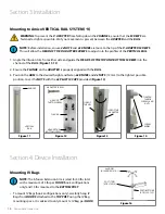
Page 8: ...before mounting Mounting to MONITOR RAIL SYSTEM MRS M 1 Lift up the INFUSION ARM and guide the MOUNTING ADAPTER into the top of the MRS RAIL as seen in Figure 5 2 Once the ARM is positioned at the de...

Page 9: ...seen through the MOUNTING ADAPTER CHANNEL secure the MOUNTING ADAPTER CHANNEl to the BOTTOM ARS ADAPTER using SCREWS and LOCK WASHERS you removed in step 1 Figure 9 3 Replace the CHANNEL COVER onto t...

Page 10: ...efore installation ensure 2x NUTS and 2x KNOBS are loose to the tip of the V ADAPTER SCREWS This will allow the HEAD OF THE V ADAPTER SCREWS to adjust into the profiles of the VERTICAL RAIL 1 Angle th...

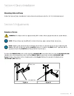
Page 11: ...ARM folded in Figure 2 PRIMARY ARM Figure 1 PRIMARY ARM SECONDARY ARM PROJECT 617 FOR USE WITH INE ___ 12 12 __ CUSTOMER Adjustments WARNING The INE ARM s has approximately 180 rotation Ensure proper...

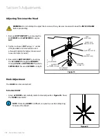
Page 12: ...HERS H WLM 10 PLATE MON CPU DISK SWIVEL DISK MON SWIV DISK NUT H LNUT M8 NYL FL ADAPTER END T 617 FOR USE WITH INE ___ 12 12 __ Adjustments WARNING The INE ARM s has approximately 180 rotat NOTE If th...

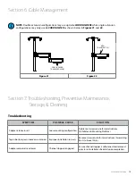
Page 13: ...USE WITH INE ___ 12 12 __ __ CUSTOME Cable Management For cable management please refer to AHM FIT_ ___ __ __ Project 481 user manual for routing cables through CORD HOLDER Please note however that th...

Page 14: ...chemical directly onto the Infusion Extension Arm Apply onto a soft cloth and wipe clean to prevent chemicals getting into the internal components of the Infusion Extension Arm The mounting assembly c...

Page 15: ...d by Amico Accessories Inc A valid Return Goods Authorization RGA number must be obtained from Amico Accessories Inc prior to commencement of any service work Warranty work which has not been pre auth...

Page 16: ...IM INFUSION EXTENTION ARM 09 26 2022 Amico Accessories Inc 85 Fulton Way Richmond Hill ON L4B 2N4 Canada Toll Free Tel 1 877 264 2697 Tel 905 763 7778 Fax 905 763 8587 Email info amico accessories co...

Reviews: