Industry Cellular Gateway
1.6.3 Connecting Power
The
IOG761 series product c
an be powered by connecting a power source to the terminal block.
It supports
dual 9 to 48VDC power inputs
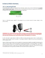
. Following picture is the power terminal block pin assignments. Please check
carefully and connect to the right power requirements and polarity.
There is a DC12V/2A power adapter
in the package for you to easily connect DC power adapter to this
terminal block.
WARNNING: This commercial-grade power adapter is mainly for ease of powering up the purchased device
while initial configuration. It’s not for operating at wide temperature range environment. PLEASE PREPARE
OR PURCHASE OTHER INDUSTRIAL-GRADE POWER SUPPLY FOR POWERING UP THE DEVICE.
For the dual power supply design on PWR1 and PWR2, the primary/backup power mode is implemented. If
there is only one power source, no matter it is connected to PWR1 or PWR2, the device can be powered up
with the power source.
However, if there are two power sources available and connected to both PWR1 and PWR2 simutaneously, the
device will choose PWR1 as the primary power, and supply required power to the entire system. The PWR2 is
treated as a backup power source, and the device will seamlessly switch to use the PWR2 as the power source
for the device when there is a power failure on PWR1. Whenever PWR1 is recovered, it will continue to supply
the required power to the system since PWR1 is the treated as the primary power source.
5 The maximum power consumption of IOG761 series product is 15.5W.
P
W
R1
G
ND
P
W
R
2
G
ND
18


