LoRa Node
10
1.6 Hardware Installation
Hereunder list the available H/W ports of IOT400:
•
LoRa:
1* LoRa node module, LoRaWAN protocol supported
•
Analog Input:
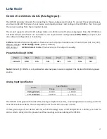
3* AI ports (supports 0-10V / 4-20mA)
•
Digital Input:
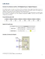
2* DI ports (isolated, supports Pulse Counter, Dry Contact)
•
Digital Output:
1* DO port (isolated, Non-Relayed Output), reserved (not available yet)
•
Field Bus:
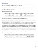
1* RS-485 for Modbus RTU/ASCII
•
Console Port:
1* RS-232 for device configuration
•
Wake-up Port
: 1* internal Reed Switch, and
1* dedicated DI for external device wake-up triggering.
•
Power Source :
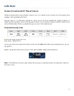
4000mAh 3.6V Li-SOCL2 battery
, or
external 5V~12V DC power.
This section describes how to install and configure the hardware.
1.6.1 Open the Top Cover
The
IOT400 series is design for universal data logging use. There are various interfaces for connecting to your
field devices, and enclosed with an IP65 grade enclosure. All the connection cables to the field devices must be
wired properly through the M16 connectors.
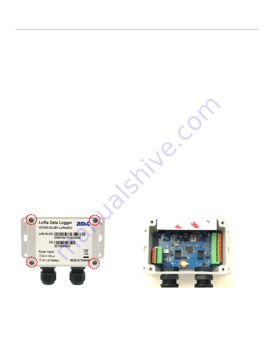
Therefore, prior to connecting and configuring the IOT400, you have to open the top cover to get access to the
control board.
Unscrew the four screws and remove the top cover to the side carefully.
You can see there are lots of hardware connectors available for you to configure. There are two spring-type
Terminal Blocks, Battery Stand, Power Socket and Switch, etc...


