LoRa Node
11
Internal View
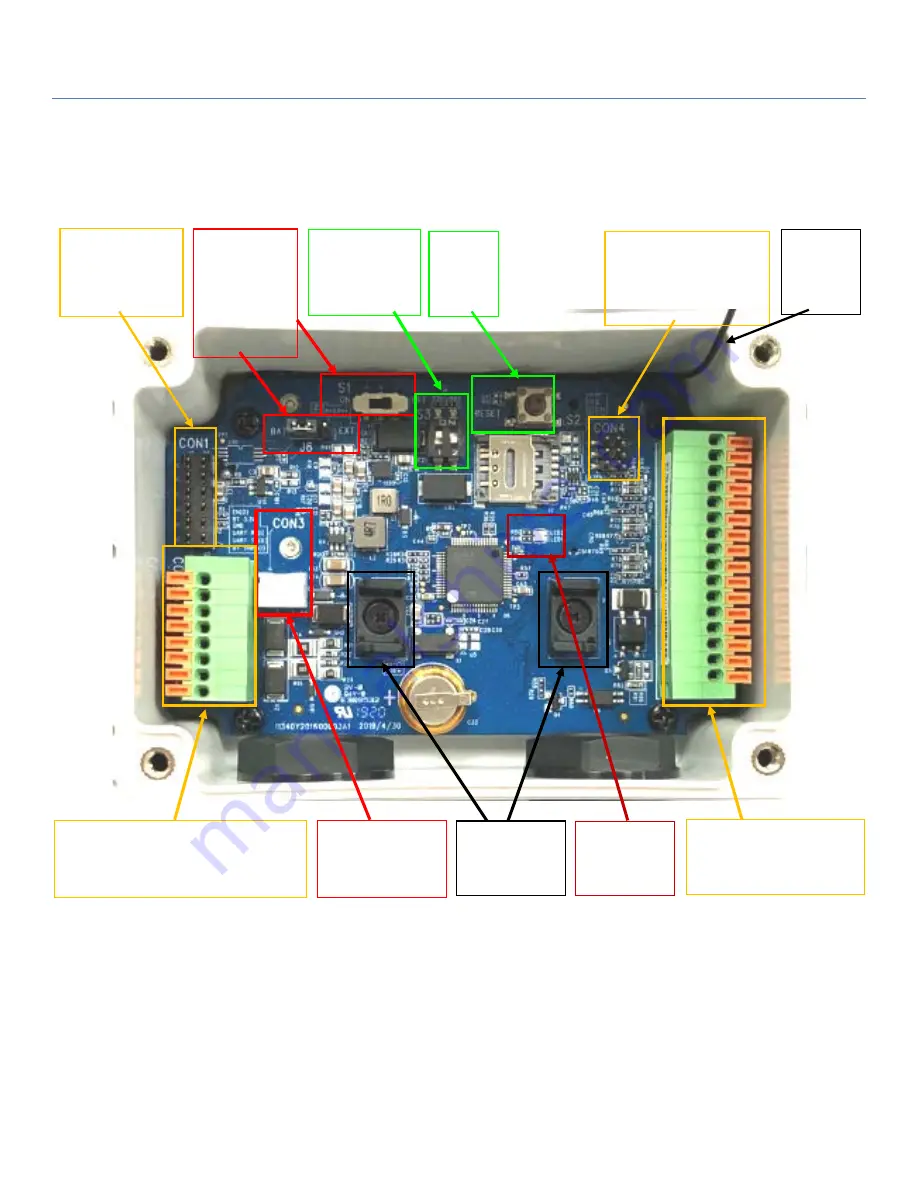
After remove the top cover, you can see all the available hardware connectors.
Note
:
1. By default
S1
(Power Switch) is in
OFF
state, and
J6
(Power Source) is in
BAT
state.
2. Before proceed to the following H/W configuration details, be sure to keep
S1
at
OFF
state till the moment
you finished the required configuration and need to Power Up the device.
3.
The
RESET
button provides user with a quick way to reboot the device.
S1:
Power Switch
(ON/OFF)
J6:
Power Source
Jumper
S2:
RESET
Button
S3:
DIP switch for
optional conf.
CON1:
2x6 headers for
device
configuration
CON2:
8-pin spring-type Terminal Block
for RS485, ext. power, wake-up
trigger
CON3:
Battery Power
Socket
CON4:
2x3 headers for AIs.
w/o Jumper: 0-10V
/w Jumper: 4-20mA
CON5:
16-pin spring-type
Terminal Block for I/Os
Battery Stand
Status LEDs
Antenna
Cable


