9
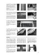
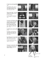
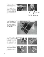
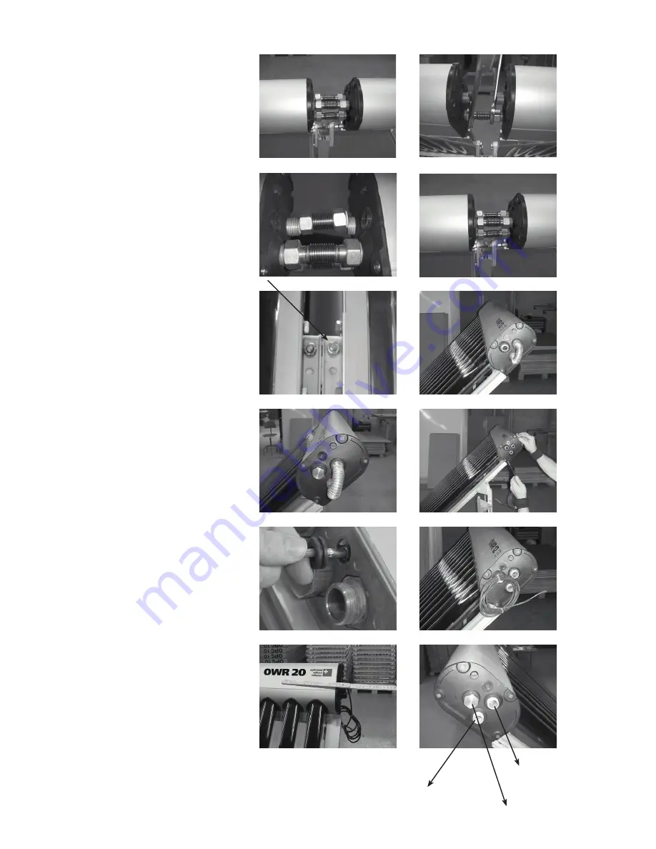
Slight tilting makes it easier
to attach the expansion joints,
whereupon the seal must not
become damaged.
All three expansion joints are
to be installed in a voltage-free
state.
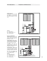
Only now is the T-head bolt on
the collector hook to be screwed
tight. At the lower end of the
collector, the clamps are now to
be pushed in and tightened.
At the collector array end, the U-
bend is to be screwed in place.
This connects the upper pipe
with the central pipe (torque
max. 15 Nm).
The blind cover is also to be
screwed in place. (torque max.
15 Nm)
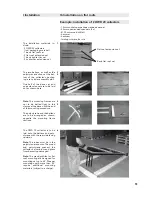
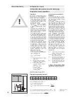
The sensor is to be inserted on
the collector's input and output
side. This requires piercing the
rubber plug, for example with a
5mm drill bit.
The rubber plug is to be com-
pletely pulled out, in order to
make sure that the sensor is
inserted into the sensor well.
The sensor is then to be inserted
together with the plug.
The sensor is to be pushed into
the collector up to the stop, i.e.
approximately 19 cm. This is the
correct position for precise tem-
perature recording.
31
32
33
34
35
36
37
38
39
40
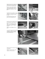
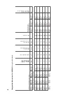
Some pressure must be applied
to insert the other expansion
joints.
All expansion joints must be
tightened at both ends diametri-
cally opposed in order to pre-
vent excessive tightening on one
side! (torque max. 15 Nm)
29
30
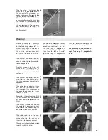
C
Collector outlet /
hot
B
Collector inlet /
cold
A
Internal
return pipe /
collector inlet


