20
Pr
essur
es and w
at
er intak
e
Pre c
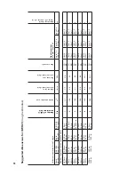
harge pressure of empty tank = static height in mwc (metres w
ater column) + 0.5 bar
Operating pressure = system fill (cold = tm max. 45°C) = pre c
harge pr 0,2 bar
The values gi
ven in the table are the number of litres until whic
h a pressure of 3.0 bar is reac
hed.
W
ater intak
e in litres / 6 bar safety valve
The capacities of other br
ands ma
y dif
fer fr
om those in this table (Pneumat
ex expansion v
essels)!
Pre c
harge pressure in tank
(bar)
1
1.
1
1.
2
1.
3
1.
4
1.
5
1.
6
1.
7
1.
8
1.
9
2
2.1
2.2
2.3
2.4
2.5
2.6
2.7
2.8
2.9
Static height (mwc)
≤ 5
6
7
8
9
10
11
12
13
14
15
16
17
18
19
20
21
22
23
24
SD = w
all-mounted tanks
SD 8
4.0
3.8
3.6
3.4
3.2
3.0
2.8
2.6
2.4
2.2
2.0
1.
8
1.
6
1.
4
1.
2
1.
0
0.8
0.6
0.4
0.2
SD 1
2
6.0
5.6
5.4
5.0
4.8
4.4
4.2
3.8
3.6
3.2
3.0
2.6
2.4
2.0
1.
8
1.
4
1.
2
0.9
0.6
0.3
SD 1
8
9.0
8.5
8.1
7.
6
7.
2
6.7
6.3
5.8
5.4
4.9
4.5
4.0
3.6
3.1
2.7
2.2
1.
8
1.
4
0.9
0.5
SD 25
12.5
11
.8
11
.3
10.5
10.0
9.3
8.8
8.0
7.
5
6.8
6.3
5.5
5.0
4.3
3.8
3.0
2.5
1.
9
1.
3
0.6
SD 35
17.
5
16.5
15.8
14.7
14.0
13.0
12.3
11
.2
10.5
9.5
8.8
7.
7
7.
0
6.0
5.3
4.2
3.5
2.6
1.
8
0.9
SD 50
25.0
23.5
22.5
21
.0
20.0
18.5
17.
5
16.0
15.0
13.5
12.5
11
.0
10.0
8.5
7.
5
6.0
5.0
3.8
2.5
1.
3
SD 80
40.0
37
.6
36.0
33.6
32.0
29.6
28.0
25.6
24.0
21
.6
20.0
17.
6
16.0
13.6
12.0
9.6
8.0
6.0
4.0
2.0
SU = standing tanks
SU 1
40
70.0
65.8
63.0
58.8
56.0
51
.8
49.0
44.8
42.0
37
.8
35.0
30.8
28.0
23.8
21
.0
16.8
14.0
10.5
7.
0
3.5
SU 20
0
10
0.0
94.0
90.0
84.0
80.0
74.0
70.0
64.0
60.0
54.0
50.0
44.0
40.0
34.0
30.0
24.0
20.0
15.0
10.0
5.0
SU 30
0
150.0
141
.0
135.0
126.0
120.0
111
.0
105.0
96.0
90.0
81
.0
75.0
66.0
60.0
51
.0
45.0
36.0
30.0
22.5
15.0
7.
5
SU 40
0
20
0.0
188.0
180.0
168.0
160.0
148.0
140.0
128.0
120.0
108.0
10
0.0
88.0
80.0
68.0
60.0
48.0
40.0
30.0
20.0
10.0
SU 50
0
250.0
235.0
225.0
21
0.0
20
0.0
185.0
175.0
160.0
150.0
135.0
125.0
11
0.0
10
0.0
85.0
75.0
60.0
50.0
37
.5
25.0
12.5
SU 60
0
30
0.0
282.0
270.0
252.0
240.0
222.0
21
0.0
192.0
180.0
162.0
150.0
132.0
120.0
102.0
90.0
72.0
60.0
45.0
30.0
15.0
SU 80
0
40
0.0
37
6.0
360.0
336.0
320.0
296.0
280.0
256.0
240.0
21
6.0
20
0.0
17
6.0
160.0
136.0
120.0
96.0
80.0
60.0
40.0
20.0
Example 1: selecting the cor
rect tank v
olume
A system with a static height of 9.0mwc (metres w
ater column) and a w
ater expansion v
olume of 1
2 litres = SD 35.
Example 2: set
ting the cor
rect pressures (pre c
harge pressure and system operating pressure)
A system with a static height of 9.0mwc
=> 1
.4 bar pr
e c
har
ge pr
essur
e => 1
.6 bar syst
em oper
ating pr
essur
e when syst
em is cold.
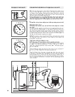
Calculation/installation of expansion vessel I
Example:
Procedure
1
Calculation of water content of solar system and expansion vessel
2
Calculation of pre charge pressure and determination of expansion
vessel
3
Filling of the solar system and adjustment of the operating pressure
(cold)
1
Calculation of water content of solar system and expansion vessel
Example data:
- Collector type
3 x OWR 20
- Water volume of solar circuit
approx. 2.5 litres
- Water volume of heat exchanger
approx. 3.0 litres
Calculation of solar system's water content:
- Collectors 3 x OWR 20; 3 x 3.5 litres
10.5 litres
- Solar circuit
2.5 litres
- Heat exchanger
3.0 litres
- Water content of solar system
16.0 litres
From these 16.0 litres, the water volume which must be taken in by
the expansion vessel is calculated:
- Thermal expansion factor F*
(5.1% of 16.0 litres)
0.8 litres
3 collectors OWR 20**
10.5 litres
11.3 litres
- Safety margin 20% of 11.30 litres
2.3 litres
- Minimum content of expansion vessel
13.6 litres
The expansion vessel must take in at least 13.6 litres.
* Water expands with the temperature increase. The thermal expan-
sion factor F indicated for 110°C in the table on p. 17 is approx.
0.051, i.e. 5.1%.
** To a large extent, the collectors' water content will transform into
vapour, see p. 18: Intrinsically safe solar system.
2
Calculation of pre charge pressure and determination of expansion
vessel
Correct calculation and setting of the pre charge pressure at the ex-
pansion vessel (air side) guarantees that the solar system will func-
tion as an "intrinsically safe solar system", p. 18.
Calculating the pre charge pressure
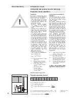
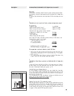
For the purposes of the calculation, the static height Hp is needed.
This is the vertical distance between the highest solar pipe and the
centre of the expansion vessel; see figure to the left. For this example,
we shall assume: Hp = 9m.
This corresponds to 0.9 bar. In addition, for reasons of safety, an over-
pressure of 0.5 bar is taken into account, thus:
pre charge pressure = 0.9 + 0.5 = 1.4 bar.
Determining the size of the expansion vessel
With the pre charge pressure of 1.4 bar, and the calculated minimum
water intake volume of 13.6 litres, the size of the expansion vessel can
be determined from the table on p. 19. Pre charge pressure of 1.4 bar,
a static height of 9 metres and a required water intake volume of 13.6
l suggest a Pneumatex SD 35 expansion vessel.

