21
SSt
EXT
T
T
P
for example p 21
for example p 21
0
1
2
3 4
5
6
bar
1
2
0
1
2
3 4
5
6
bar
for example p 21
for example p 21
0
1
2
3 4
5
6
bar
1
2
0
1
2
3 4
5
6
bar
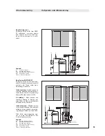
HW
CW
SSt
EXT
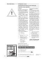
Filling station
A0
A1
3
D
B
C
E
P1, P2; 0-5 bar
Bleed valve
TMV
S1
S2
hot
cold
T
T
P
P1
P2
Calculation/installation of expansion vessel II
Example (continued):
N.B.:
The pre charge pressure (air side) at the expansion vessel is set
directly at the expansion vessel by means of a manometer. The valve
is situated in the middle of the expansion vessel. Normally, the tank
pressure is set high enough in the factory so that it only has to be
reduced to the pre charge pressure level.
The pre charge pressure is set before filling the solar circuit, and it can/
should be set before connecting the tank to the solar circuit. The mini-
mum pre charge pressure in the expansion vessel is at least 1.0 bar.
3
Filling of the solar system and adjustment of the operating pressure (cold)
Filling the solar system
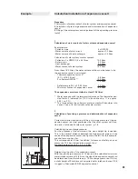
NOTE: The solar system must not be filled while subjected to direct
sunshine!
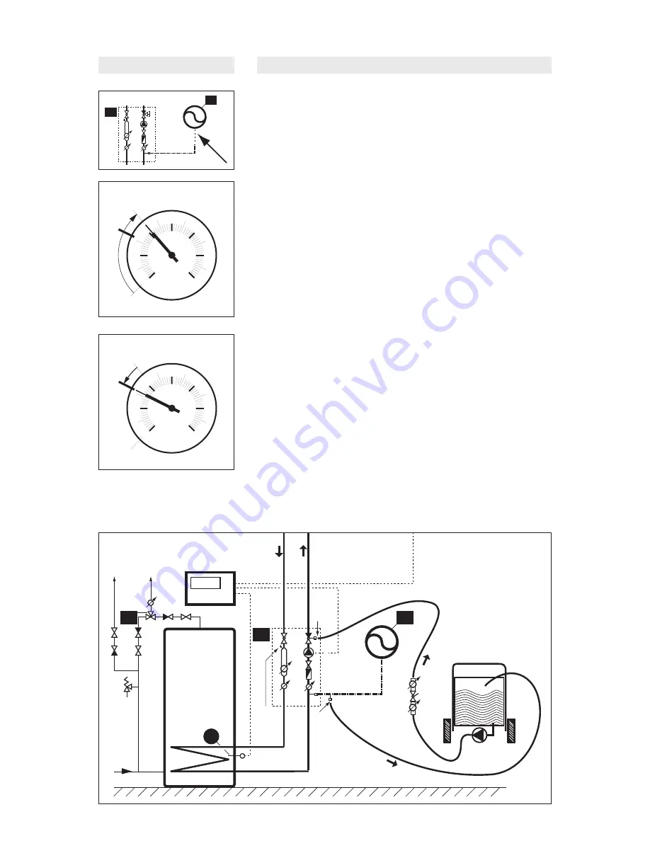
The heat transfer medium, e.g. Tyfocor, is pumped into the solar sys-
tem by pump B at filling station C at connection A0. Bleed valve 3 on
the solar station (SSt) is closed (see arrow). The heat transfer medium
flows via A1 back into filling station E. The heat transfer medium is
pumped through the solar circuit until no more air bubbles appear in
the flow of heat transfer medium at output E.
NOTE:
The pump on the solar station SSt must be turned on when
the filling pressure in the system is 1 bar or higher. This prevents the
pump from running dry.
Adjustment of the operating pressure
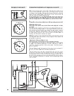
NOTE: See page 19 for calculation of the operating pressure.
The operating pressure depends on the static height. In the example
on page 19, a operating pressure of 1.6 bar is derived. In order to
reach the operating pressure in the solar system, the following pro-
cedure is applied.
1
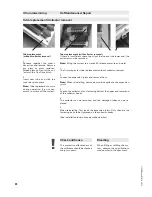
With the filling pump B, the pressure in the solar circuit is raised to 2.1
bar. This is 0.5 bar higher than the operating pressure.
2
After the filling station has been disconnected from the solar circuit
at A0 and A1, the pressure in the system is now 0.5 bar too high. By
opening bleed valve 3 at the solar SSt, the pressure is reduced to 1.6
bar; this is the operating pressure in this example. With this procedure,
the air remaining in the system is removed, and the operating pressure
is set correctly.
for example p. 19
for example p. 19

