background image

©Copyright AMKUS Rescue Systems, Inc. 2016-2019 

LAC-003 May 20, 2019 Rev05

10

9.0 ROUTINE MAINTENANCE

WARNING

Avoid contact with escaping hydraulic fl uid under pressure.  If hydraulic fl uid punctures skin, seek 
medical treatment immediately.  Contact with escaping hydraulic fl uid under pressure could result 
in serous injury or death.  

Inspect all hose, hose fittings and couplings for leakage and damage (see routine maintenance for hoses and couplings).

Using a torque wrench, tighten the socket head cap screws which hold the control valve to the valve manifold and the valve manifold 
to the hydraulic cylinder plug to 180 in/lbs (20.3 Nm).  DO NOT OVERTIGHTEN!  These screws are installed securely at the factory 
but may loosen because of vibration while being transported on moving vehicles.  

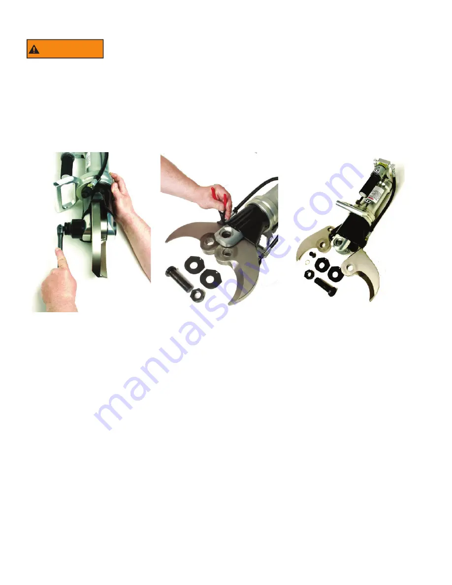
Approximately once a year, or more often if necessary, remove the cutter blades for cleaning and inspection.  Removal of the blades 
is most easily accomplished by closing the blades until the retaining rings on the drive link pins are easily accessible.

Loosen the center bolt nut. (Photo 1)  After removing the nut, push the center bolt out, being careful not to damage the threads.  
Next, remove the retaining ring (Photo 2) from the drive link pin for each blade and push each drive link pin out.  Remove the blades 
and friction plates from the body (Photo 3).

Photo 1

Photo 2

Photo 3

Clean and inspect each blade, friction plate, drive link pin, and the center bolt for signs of damage or excessive wear.  Damaged or 
worn parts may need to be replaced.  Also, clean inside the body, being sure to remove all grease and dirt.

Lubricate each blade inside the center bolt hole, the drive link pin hole, and on the surfaces where it will contact the other blade, the 
friction plate, and the drive link.  Use a general purpose white lithium grease such as Lubriplate

®

 No. 630-AA.

Position the “ear” of the blade in the drive link.  Lubricate and insert the drive link pin through the drive link and the blade.  Please 
note that the head of the drive link pin should fit into the counterbore in the drive link.  Install a 

new

 retaining ring into the groove of 

the drive link pin.  Repeat these steps for the remaining blade.

Lubricate the shaft of the center bolt.  Insert the friction plate nearest the back of the cutter. Rotate the blade into position and insert 
the center bolt through the back half of the body, friction plate, and blade. Insert the remaining friction plate

Rotate the remaining 

blade into position and push the center bolt in completely.  Be careful to line up the shape of the head of the center bolt with the 
corresponding shape in the body.  Install the hex nut onto the center bolt.  Using a torque wrench, tighten the nut to 120 ft/lbs (163 
Nm) (Photo 1). 

Summary of Contents for AMK-22

Page 1: ... before use Operating AMKUS Rescue Systems without understanding the manual receiving proper training and using appropriate personal protective equipment is a misuse of AMKUS equipment This manual does not fully address safety Additional safety information is published in AMKUS Safety Manual LAA 001 and Safety Data Sheet LAA 004 EN13204 Designation AC127F 20 9 Certified Compliant to NFPA 1936 2015 ...

Page 2: ...This manual should be available to all personnel involved with AMKUS equipment SAFETY MANUAL for AMKUS RESCUE SYSTEMS AMKUS RESCUE SYSTEMS www amkus com 4201 Montdale Drive Valparaiso IN 46383 4098 USA 800 592 6587 630 515 1800 Fax 630 515 8866 Copyright Amkus Rescue Systems Inc 2014 2016 LAA 004 December 8 2016 Rev04 SAFETY DATA SHEET According to OSHA Hazard Communication Standard 29 CFR 1910 12...

Page 3: ...G STARTED 7 6 1 ROTATING THE HANDLE 7 6 2 CONTROL VALVE ACTUATOR 7 7 0 OPERATING INSTRUCTIONS 8 8 0 SAFETY GUARDS 9 9 0 ROUTINE MAINTENANCE 10 9 1 ROUTINE MAINTENANCE FOR HOSES 9 2 ROUTINE MAINTENANCE FOR COUPLINGS 9 3 ROUTINE MAINTENANCE FOR CENTER BOLT 9 4 MAINTENANCE RECORDS 9 5 HANDLE LIGHT BATTERY REPLACEMENT 10 0 TROUBLESHOOTING 11 11 0 PARTS SERVICE AND TECHNICAL INFORMATION 12 12 0 DECOMMI...

Page 4: ...n which if not avoided could result in minor or moderate injury NOTICE NOTICE is used to address practices not related to physical injury 2 0 SPECIFICATIONS Part AMK 22 MECHANICAL SPECIFICATIONS Length 24 7 in 627 4 mm Width 7 5 in 190 5 mm Depth 8 9 in 226 1 mm Weight ready to use Ready to use with standard couplings and non lighted handle 46 0 lbs 20 9 kg Cutter Opening Distance 5 0 in 127 mm Cu...

Page 5: ...ourse of instruction acknowledged as being educationally sound by the local authority having jurisdiction over such training This document contains basic operating and maintenance instructions only 3 0 PROTECTIVE CLOTHING WARNING Always wear protective clothing Failure to do so could result in serious injury or death It is the responsibility of the user to ensure that appropriate protective clothi...

Page 6: ...onnected to the corresponding male and female couplings on the tool connection hoses To connect the couplings twist the sleeve on the female coupling so that the notch in the sleeve lines up with the pin Push the sleeve back so the pin fits into the notch While holding the sleeve back push the male coupling into the female coupling Release the sleeve it will spring forward into place Twist the slee...

Page 7: ...cutting easier and safer even in awkward situations A tension lock lever sets how much drag holds the handle position To change handle position unlock the tension and rotate the handle to the desired place The tension lock lever follows a U shaped track between locked and unlocked positions as shown on the label If the handle encounters an obstruction during cutting then the handle just moves to t...

Page 8: ...s as may be necessary for extrication However this cutter is not intended as a piercing tool for heavy metal Therefore when cutting care must be taken to insure that the tips of the blades have a clear path of travel The tips of the blades will pierce the sheet metal body panels of most automobiles but care must be taken to avoid obstacles like the heavy metal backing plates behind seat belt mount...

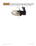
Page 9: ...rom laceration projectile high speed flying debris and pinch point injuries Stay clear of the path of travel Do not operate without guards Avoid unnecessary risk For examples see LAA 001 Safety Manual For AMKUS Rescue Tools Tools with moving blades or arms have a guard over the moving parts Do not operate rescue tools with guards missing Guard Figure 8 0 ...

Page 10: ... link pin out Remove the blades and friction plates from the body Photo 3 Photo 1 Photo 2 Photo 3 Clean and inspect each blade friction plate drive link pin and the center bolt for signs of damage or excessive wear Damaged or worn parts may need to be replaced Also clean inside the body being sure to remove all grease and dirt Lubricate each blade inside the center bolt hole the drive link pin hol...

Page 11: ... ROUTINE MAINTENANCE FOR COUPLINGS Keep hose couplings free of dirt and contaminants Even with care residual oils on the moving parts gradually accumulate dirt and grit making hose connections difficult To clean hose couplings immerse in or scrub with an automotive type aerosol solvent degreaser Apply a light spray lube automotive lock or gun type to keep the collars moving easily The rubber dust ...

Page 12: ...hecklist 1 Check to see that important tool markings are legible Contact your local dealer or AMKUS Rescue Systems for replacement labels 2 Wipe tool hoses fittings and couplings clean see routine maintenance for hoses and couplings 3 Inspect the rescue tool hoses fittings and couplings after each use for damage leakage and excessive wear 4 If rescue tool damage or excessive wear is noticed remove t...

Reviews: