background image

©Copyright Amkus Rescue Systems, Inc. 2018-2020 

LAA-002 March 10, 2020 Rev02

4

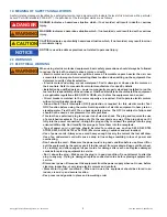
1.0 MEANING OF SAFETY SIGNAL WORDS

A safety related message is identi

fi

 ed by a safety alert symbol and a signal word to indicate the level of risk involved with a particular 

hazard. Per ANSI standard Z535.6-2011, the de

fi

 nitions of the four signal words are as follows:

DANGER

DANGER indicates a hazardous situation which, if not avoided, will result in death or serious 
injury.

WARNING

WARNING indicates a hazardous situation which, if not avoided, could result in death or serious 
injury.

CAUTION

CAUTION indicates a potentially hazardous situation which, if not avoided, may result in minor 
or moderate injury.

NOTICE

NOTICE is used to address practices not related to personal injury.

2.0 WARNINGS
2.1 ELECTRICAL WARNING

WARNING

When using electric motorized equipment, basic safety precautions should always be followed 
to reduce the risk of 

fi

 re, electric shock, injury, or death;

• Electric motor and controls are ignition sources. Flammable vapors heavier than air can 

accumulate in low spots. Avoid selecting these locations when setting up the equipment. Use 
detectors to verify safe site selection.

•  Electric motor and wiring are not waterproof. Don’t submerge or douse electric motors or 

their controls. Refer to manuals from motor manufacturer for speci

fi

 c details.

• Installation by quali

fi

 ed person – power componentry properly sized and installed to run the 

tool are the responsibility of the purchaser. Quali

fi

 ed electricians should install the equipment 

per applicable regulations (NEC, NFPA, OSHA, etc.) before the equipment can be used.

• Circuit breakers matched to the motor capacity are required. Don’t operate electric motors 

without circuit breaker protection.

• Ground Fault Circuit Interrupter (GFCI) protection is required for this electric motor. Test 

GFIC function before using the motor. Avoid operation of electric equipment in heavy rain or 
standing water. Treat the GFCI as a backup safety device. The GFCI is subject to failure and 
should not be used as a replacement for safe practices.

• This tool has a polarized plug to reduce risk of electric shock. The plug and requires the use 

of a matched receptacle. The plug only 

fi

 ts the receptacle one way. If the plug does not 

fi

 t 

fully into the power connection, re-align the plug and try to reinsert the prongs into the plug 
oriented di

 erently. Don’t modify the prongs or force them into the receptacle.

• Type of power cord - cord type should be rated for outdoor use, such as SW, SOW, STW, 

STOW, SJW, SJOW, SJTW, or SJTOW. (W service rating = outdoor and wet location)

• Use of power cords - Always use a cord heavy enough to carry the current the tool will draw. 

Use of an undersized cord will cause a drop in line voltage resulting in loss of power and 
overheating.

• Don’t abuse the cord – Make sure the power cord is in good condition before use. Never lift or 

pull the equipment by the cord or yank it to disconnect from receptacle. Keep cord from heat, 
oil, crushing, and sharp edges. Inspect cords for damage after each use. Replace damaged 
cords before placing equipment in service.

• Don’ t abuse the plug – Make sure the plug is in good condition. Do not attempt to alter the 

plug in any way. If plug is damaged replace connected cords before placing equipment in 
service.

• Disconnect power –Disconnect the equipment from the power supply when not in use, before 

cleaning, inspecting, or servicing electric motors and controls.

• Store motor in good conditions – When not in use, the equipment should be stored in an 

indoor, clean, dry, and secure location.

• Keep covers and guards in place and in working order

Summary of Contents for ARRS-1

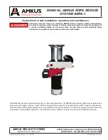
Page 1: ...Electrically driven capstan operated hoist system for rope rescue operations The AMKUS Rope Rescue System may be paired with a truck mounted monopod a bipod or tripod Refer to manuals for these devices when operating the ARSS 1 paired to these devices This manual does NOTaddress operation or servicing ofAMKUS Rope Rescue Systems Only competent rescue tool repair technicians are qualified to repair...

Page 2: ...operable condition and has been maintained in accordance with the manufacturer s instructions 6 Failure to follow these guidelines may result in death burns or other severe injury FEMSA Fire and Emergency Manufacturers and Service Association P O Box 147 Lynnfield MA 01940 www FEMSA org This manual does NOT address operation or servicing of AMKUS Rope Rescue Systems Only competent rescue tool repa...

Page 3: ... SET UP PROCEDURE 6 2 ROPE SELECTION 7 0 ROPE SETUP AND GETTING STARTED 7 1 HOIST WRAPS 7 2 IMPACT FORCES 7 3 GETTING STARTED 8 0 OPERATING INSTRUCTIONS 8 1 CONTROLLING A LOAD 8 2 LOWERING A LOAD 8 3 RAISING A LOAD 8 4 TENDING PRUSIKS 8 5 ROPE WRAPS AND PREVENTING OVERLAP 9 0 TROUBLESHOOTING GUIDE 10 0 ROUTINE MAINTENANCE 10 1 MAINTENANCE RECORDS 11 0 PARTS SERVICE AND TECHNICAL INFORMATION 12 0 D...

Page 4: ...s without circuit breaker protection Ground Fault Circuit Interrupter GFCI protection is required for this electric motor Test GFIC function before using the motor Avoid operation of electric equipment in heavy rain or standing water Treat the GFCI as a backup safety device The GFCI is subject to failure and should not be used as a replacement for safe practices This tool has a polarized plug to r...

Page 5: ...evere injury or death Always use a rope with a minimum breaking strength per NFPA 1983 WARNING Do not use a rope that fails any part of the rope inspection listed in section 11 1 Rope that fails under tension will release stored energy violently potentially causing severe injury or death Before any operation check the entire length of rope according to section 11 1 WARNING Do not keep the rope sta...

Page 6: ... supply requirement 115 V A C 20 Amps Full load draw 14 Amps 60 hz Receiver hitch requirement 2 x 2 Minimum Class IV Rated with a minimum capacity of 10 000 lbs 4535 kg Rope Requirement rescue rope 1 2 to 5 8 12 7 mm to 15 88 mm Rope Minimum Breaking Strength Per NFPA 1983 Maximum rope Speed 40 feet per minute up to full load 12 m min up to full load 3 1 PART IDENTIFICATION Capstan Upper Sheave Le...

Page 7: ... If however you have decided to place the equipment into service yourself please review the following instructions carefully The ARRS1 is delivered with the following components Capstan hoist assembly Foot switch Hitch extension Hitch pins 2 1 Remove equipment from the packing cartons and carefully inspect for damage Damage that occurs during shipment should be reported immediately to the carrier ...

Page 8: ...e rope the greater the magnification The farther the drop the greater the magnification A typical Life Safety rope with a moderate load can experience more than a doubling of tension if the load is allowed to drop even a few inches Always use dual tandem Prusiks to minimize any free fall distance 7 3 GETTING STARTED 1 Slide the hitch extension into the vehicle mounted hitch receiver Align the hole...

Page 9: ... capstan is rotating apply pulling force to the tail or fall line of the rope Continue to pull the tail line until the load is raised to the desired position Release the foot switch 8 4 TENDING PRUSIKS Tending the Prusiks is an important part of operating the ARRS 1 Depending on how well the Prusiks are tended free fall distances can be between a fraction of an inch up to 12 inches Keep all body p...

Page 10: ...radio into it and determine if the foot switch will turn the device on and off If motor still will not operate contact your local AMKUS Rescue Systems dealer Foot switch will not operate Check to ensure foot switch is plugged in correctly Contact your local AMKUS Rescue Systems dealer for replacement switch Hoist lacks power or slows during operation Ensure the load does not exceed the hoist s work...

Page 11: ... until it is discarded The following information if applicable must be included on the test record for each rope rescue system 1 Assigned identification number 2 Manufacturer 3 Product or model designation 4 Vendor 5 Warranty 6 Date received and date put in service 7 Date of each service test and service test results 8 Damage and repairs including who made the repairs and the cost of repair parts ...

Page 12: ... 14 0 INSPECTION CLEANING DECONTAMINATION AND STORAGE Always store the tool securely in a clean dry space Disconnect power source BEFORE BEING PLACED BACK IN SERVICE the rescue tool must be inspected to this list Check to see that all rescue tool markings are legible o Contact your local dealer or AMKUS Rescue Systems for replacement labels Wipe the tool clean using fresh water If the rescue tool ...

Reviews: