background image

2

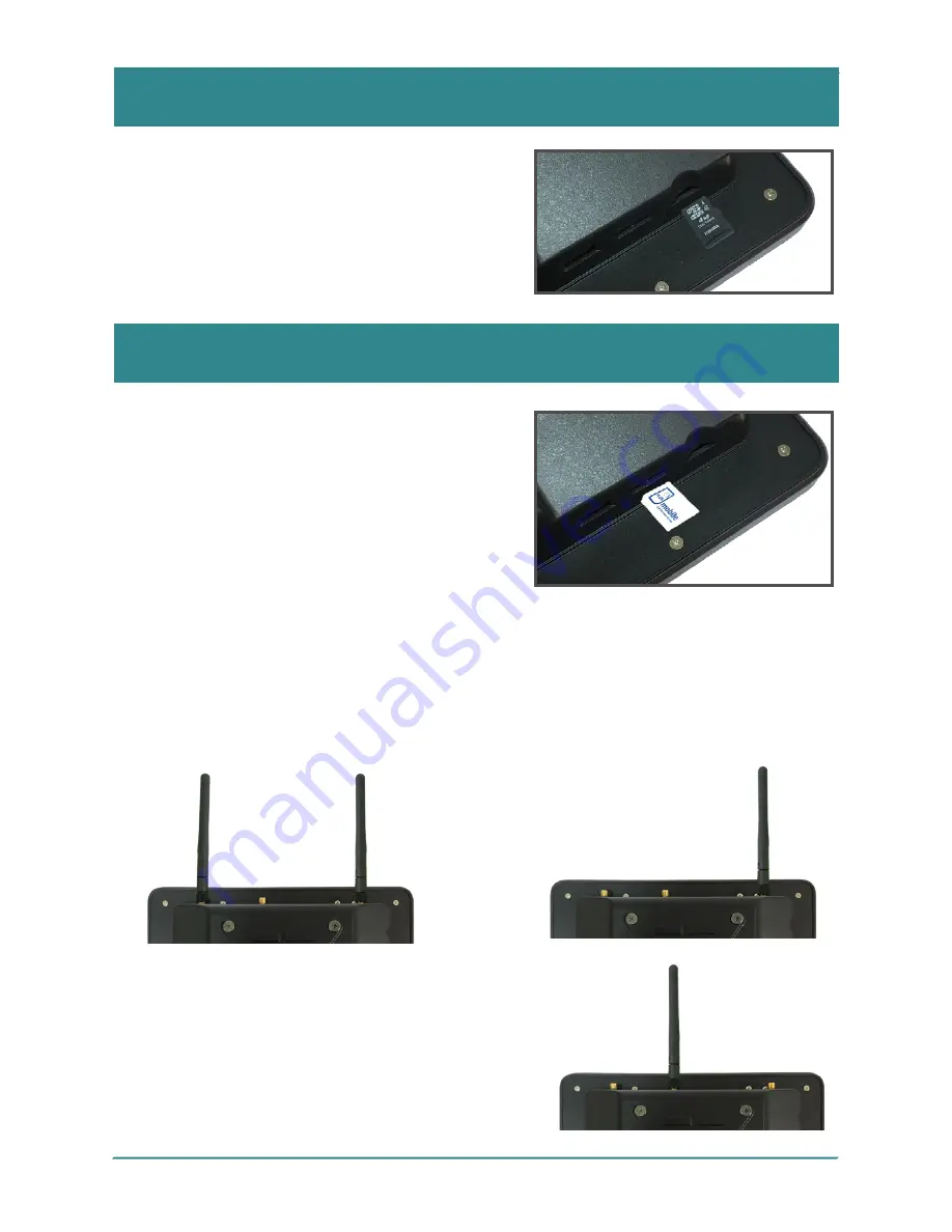
Install microSD Card

Install SIM Cards & Antenna

To install a microSD card to the device, locate 

the microSD card slot on the side and insert 

the card following the direction as shown in 

the picture. Push the card into the slot until it 

locks into place.

SIM Card Installation

The IOT-800 accepts micro SIM (3FF) card. 

To install a SIM card to the device, locate the 

SIM card slot on the side and insert the card 

following the direction as shown in the picture. 

Push the card into the slot until it locks into 

place.

3G/4G Antenna Connection

According to the type of mobile network supported by your IOT-800, attach 

appropriate antenna to the IOT-800.

The IOT-800 comes with a Wi-Fi/Bluetooth 

antenna to help increasing the signal strength. 

To use the antenna, attache the Wi-Fi/

Bluetooth antenna to the Wi-Fi/Bluetooth 

antenna connector.

Wi-Fi/Bluetooth Antenna Connection

To use 4G mobile network, attach 
two 4G antennas as shown below.

To use 3G mobile network, attach one 
3G antenna as shown below.

Wi-Fi/Bluetooth 

Antenna

3G Antenna

4G Antennas

Summary of Contents for IOT-800

Page 1: ...IOT 800 8 Risc based Panel PC User Manual...

Page 2: ...written permission of the manufacturer Disclaimer The information in this document is subject to change without prior notice in order to improve the reliability design and function It does not repres...

Page 3: ...eption which can be determined by turning the equipment off and on the user is encouraged to try to correct the interference by one or more of the following measures Reorient or relocate the receiving...

Page 4: ...le switch 7 2 pin DC terminal connector 12V 24V auto detection 17 4G antenna connector 8 microSD card slot 18 Wi Fi Bluetooth antenna connector 9 Micro SIM 3FF slot 19 3G 4G antenna connector 10 UART...

Page 5: ...the direction as shown in the picture Push the card into the slot until it locks into place 3G 4G Antenna Connection According to the type of mobile network supported by your IOT 800 attach appropriat...

Page 6: ...length for the DC power connector 2 Insert the wires into the DC power connector terminals and use a screwdriver to tighten the two captive screws on the connector Pin Description 1 Power_GND 2 12V 3...

Page 7: ...CAN Bus Description Digital General Purpose Signal Input Output and CAN 10 1 Connector Type 4x 3 3V Digital GPIO connector and 1 x CAN 2 0b Bus Pin Description Pin Description 1 IO_GND 6 GPIO_4 2 GPI...

Page 8: ...io communications However there is no guarantee that interference will not occur in a particular installation If this equipment does cause harmful interference to radio or television reception which c...

Reviews: