background image

www.amp-research.com

IM75163 rev 01.02.20

2/10

A M P   R E S E A R C H   P O W E R S T E P

T M

  –     S P R I N T E R

INSTALLATION GUIDE

Attaching motor to linkage assembly

The motors must be attached to the linkage assemblies before continuing the 

installation process.

CAUTION: HANDLE WITH CARE.

To ensure our customers receive all components with full integrity, we pack the motors separate from their linkage 

assemblies. This requires that the installer position and fasten the motor before continuing with the install. Please 

follow the instructions below and handle the assembly carefully.

CAUTION: Dropping the assembly or any excessive impact MAY cause damage to the motor.

Instructions:

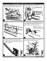
1. Position the gear cover in place as shown if not already in place.

2. Seat motor into position on the three mounting bosses. This may require an adjustment of the gear by moving the 

swing arms.

3. After seating into place, fasten the motor with the three motor mount screws with 4mm Hex Head. Tighten screws to 

36 in-lbs (4N-m). 

Do not over torque.

EXPLODED VIEW

• Motor

• Socket cap screw

• Washer

• Drive Gear Housing Cover

Summary of Contents for 75163-01A

Page 1: ...on q Wire stripper cutter q 3 16 hex key allen wrench q 4mm hex key allen wrench q Electrical tape SKILL LEVEL 4 Experienced 1 2 3 4 INSTALLATION TIME AMP RESEARCH TECH SUPPORT 1 888 983 2204 Press 2 Monday Friday 7 00 AM 5 00 PM PST 5 Year Limited Warranty WARRANTY Invented engineered and manufactured exclusively by AMP Research in the USA May be covered by one of the following patents 6 641 158 ...

Page 2: ... position and fasten the motor before continuing with the install Please follow the instructions below and handle the assembly carefully CAUTION Dropping the assembly or any excessive impact MAY cause damage to the motor Instructions 1 Position the gear cover in place as shown if not already in place 2 Seat motor into position on the three mounting bosses This may require an adjustment of the gear...

Page 3: ...S P R I N T E R 2 Motor Linkage Assembly 3 Idler Linkage Assembly 1 Running board assembly D B A End cap left x1 B End cap right x1 C T nut insert x2 D Socket cap screw x2 E End cap wedge right x1 F End cap wedge left x1 A C E F 4 Wire Harness 5 Controller STA 6 x4 M8 Hex bolt 7 x4 Washer SS ...

Page 4: ...L TEMPLATE Use center punch pilot drill 1 8 then drill final hole size 17 32 8 x4 Socket Cap Screw 9 x20 Cable Tie 7 10 x2 Cable Tie 11 PARTS LIST AND HARDWARE IDENTIFICATION 12 x4 M8x12 Flange Bolt 14 x2 Large Washer 11 x2 Posi TapTM Connector 17 x4 Butt Connector 16 x2 LED Lamp 13 x2 M8x25 Flange Bolt 18 Rivet Nut Tool 15 x6 M8 Rivet Nut 19 Rear Support Bracket 20 Front Support Bracket ...

Page 5: ...Rear Drive Linkage install Locate rear linkage location Clean undercoating so any proud edges are knocked off and mounting surface is flat Set Upper mount up to bump in sheetmetal and mark side of linkage near mounting slot Warning Rivet nuts not properly collapsed will not hold securely to sheet metal Set rear linkage over bolts Using a 13mm box wrench snug up two bolts on linkage Using supplied ...

Page 6: ...vet nuts into position Refer to install card in rivet nut tool bag Then pre thread m8 screws and washers into position Warning Rivet nuts not properly collapsed will not hold securely to sheet metal Using supplied Flange bolts install bracket onto Idler linkage Upper mount Do not tighten to allow for adjustment Use shorter bolts to prevent bolt and linkage arm interference 13mm Set front idler lin...

Page 7: ...nstall rivet nut Install longer flange bolt and reassemble bolts on bracket at linkage With front bracket in place mark hole Center punch Pre drill with 1 8 and then final drill to 17 32 Install rivet nut Install longer flange bolt and reassemble bolts on bracket at linkage Note 2 Washers are provided to space out multiple layers of sheetmetal Mount controller under vehicle attach to loom that run...

Page 8: ...t and Tighten Splice Power Step trigger wires into the Door Ajar wires with provided Posi TapTM splicers The Power Step trigger wires color coordinate with the factory Door Ajar wires Follow the steps below to correctly splice wires Route remaining wires up and over exhaust heat shield and back along passenger side to motor Remove side access panel Locate grommet under passenger side seat Pull tri...

Page 9: ...ont LED Light and 60 for the rear LED Light Affix lamp 16 to rocker panel surface Make sure lamp is affixed to a flat clean surface Front Door Located in the loom in passenger foot well Remove mat covering jack Route Blue Trigger wire up through opening in side of seat base Route under floor paneling and route up towards foot well Factory wire will be Blue with a Green stripe Drill a 9 32 hole thr...

Page 10: ...will illuminate upon opening any door of vehicle Lamps will stay on until restowing of both Power Steps or until 5 minutes has expired with the doors open When the lights timeout after 5 minutes they can be reillumintated by closing and opening any door of vehicle FINAL SYSTEM CHECK Check that all doors activate the PowerStep and the LED lights work when doors open and close NORMAL OPERATION When ...

Page 11: ... product itself or the repair or replacement of any component part thereof found by the factory to be defective within the time period specified The decision to repair or replace is wholly within the discretion of the manufacturer for instructions You must retain proof of purchase and submit a copy with any items returned for warranty work Upon completion of warranty work if any we will return the...

Reviews: