12
4.8.2. V-nail guide head replacement to
change V-nails size
The V-nail guide head must be changed each time
you use V-nails of different sizes.
Proceed as follows to change it:
•
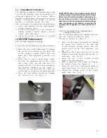
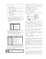
Move the claw pusher backwards by flipping
the special lever located on the right side
of the machine working bench, this will
permit access to the nail magazine (see
fig. 6).
•
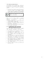
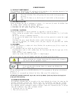
Remove all the V-nails that are still in the
magazine (using the proper brass magnet, if
necessary) (see fig.10).
•
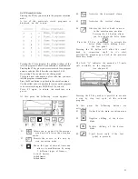
Insert the new V-nail stick(of desired
height) into the magazine
•
Move forward the claw pusher by flipping
the control lever (see figure 6).
•
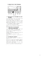
Insert the new size V-nail guide head to
match the V-nails to be used (see fig. 11).
•
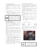
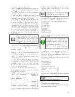
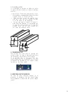
Tighten the locking screw of the V-nail
guide head (see fig.8).
4.8. MACHINE ARRANGEMENT
4.8.1 V-Nails magazine loadiing
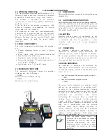
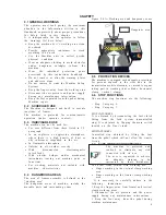
To load the V-nail magazine proceed as follows:
•
Move the claw pusher backwards by flipping
the special lever located on the right side
of the machine working bench. This will
make the V-nail magazine accessible (see
fig. 6).
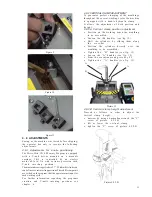
•
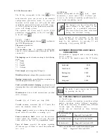
Insert one or more V-nails strips, taking
care that the sharpened edge of the V-nails
(glue side) faces up and that they are
loaded with the V of the V-nails pointing in
the direction indicated in the figure 7.
You also need to check that the v-nail size
is the same as the type of claw head mounted.
•
Move the claw pusher forward by flipping
the control lever (see figure 6).
TAKE CARE: When the magazine runs short of
V-nails, or when it contains an amount of V-nails
that is not sufficient to complete a working cycle,
the machine will stop at the next foot-pedal
pressure and warn the operator with three beeps
and a message on the display- informing the
operator that magazine is running short of V-
nails.
Figure 8
Figure 7
Figure 6
4.7
PRELIMINARY CONTROLS
The Machines preliminary operations before you
1st start the machine, must be executed by a
technician appointed by the customer. Before
machine commissioning, it is necessary to execute
certain verifications and checks to prevent
mistakes or accidents during the setup.
The verifications to execute are the followings:
•
Verify that machine has not been damaged
during assembly steps.
•
Verify with extreme care, the integrity of
electric boards, control panels, electric
cables, wires and pipes
•
Check the proper connection of external
power sources
Summary of Contents for Mitre-Mite VN4 MemoryProgram
Page 1: ......
Page 32: ...32...
Page 33: ...33...
Page 38: ...38 ATTACHMENT C PLATES DISLOCATION...
Page 41: ...41...


