13
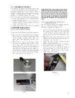
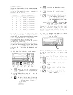
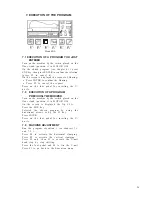
Figure 9
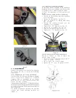
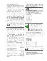
Figure 10
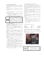
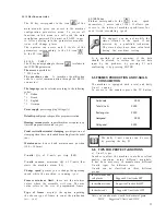
Figure 11
4 . 9 ADJUSTMENTS
Seeing as the machine was tested before shipping,
the operator has only to execute the following
a d j u s t m e n t s :
4.9.1 Adjustments for v-nails positioning
The Mitre-Mite VN 4 Memory Program is equipped
with a V-nail driver mounted on a movable
carriage. This is controlled by an electric
motor able to fix with extreme precision each
V-nail inserting position.
The maximum carriage stroke is 5.7”. Within this stroke you
can define several inserting positions. These different points
are settled on the program that the operator must input for
each working cycle.
For further information regarding the programs
creation and V-nails inserting positions see
chapter 6.
4.9.2 VERTICAL CLAMP ADJUSTMENT
To guarantee perfect clamping of the mouldings
throughout the several working cycles the machine
is equipped with a double hydraulic clamp.
It allows the adjustment of both position and
h e i g h t .
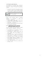
4.9.2.A Vertical clamp position adjustment
•
Position on the working bench the moulding
to be assembled
•
Loosen the (B) handles (see fig 12)
•
Shift the cylinders, by sliding them along
the cross-bar.
•
Position the cylinders directly over the
moulding to be assembled.
•
Tighten the “B” handles (see fig. 12)
•
Loosen the “A” handles (see fig. 12)
•
From the execution menù press key F5
•
Tighten the “A” handles (see fig. 12)
Picture 12
A
B
A
B
4.9.2.B Vertical clamp height adjustment
Procced as follows, in order to adjust the
vertical clamp height:
•
unscrew by using a 6mm allen wrench the “C”
screw of picture 4.9.2.B
•
lift or lower the vertical clamp
•
tighten the “C” screw of picture 4.9.2.B
Picture 4.9.2.B
Summary of Contents for Mitre-Mite VN4 MemoryProgram
Page 1: ......
Page 32: ...32...
Page 33: ...33...
Page 38: ...38 ATTACHMENT C PLATES DISLOCATION...
Page 41: ...41...


