background image

30

9 . 2 . e

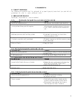
The electronic part does not work

Possible cause

Remedy

Machine disconnected from the electric network or
one or more interrupted fuses

t

 Connect the machine with the electric network


t

 Unscrew the panel located on the rear side of

the oorstand: verify by using a tester the

fuses continuity and replace it if necessary

1. Network  lter board M003/x: delayed 4A fuse

(mod. 5x20 glass)

2. Board M021/x....F1 delayed 10A fuse (mod. 5x20 glass)

3. F2 delayed 6,3A fuse (mod. 5x20 glass)

Wrong voltage

t

 connect the machine to a 120 V socket

If t h e

a b o ve

list e d

co n d it io n s

a re

co rre ct

a n d

t h e

fa ilu re

st ill e xist s

t

call AMP or your local distributor’s Assistance service

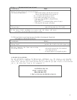
9.2.f Wishing to insert several V-nails one upon the other in the same point, they do not
            stack properly or tilt during their insertion

Possible cause

Remedy

Wro n g  V-n a ils

t

re p la ce t h e V-n a ils wit h t h e p ro p e r o n e s

Im p ro p e r cla m p in g , (t h e fra m e m o ve s d u rin g
the insertion of V-nails)

t

verify and if necessary adjust the vertical and

fr

ontal clamps positions

t

 increase the pressure by using the regulator

9.3 REQUEST OF ASSISTANCE

Fo r a n y in fo rm a t io n re g a rd in g Use , Ma in t e n a n ce , In st a lla t io n , e t c.. We re m a in a t yo u r d isp o sa l.
Th e Cu st o m e r h a s t o fo rm u la t e cle a rly t h e q u e st io n s. Ca ll o r Se n d u s  a   d e t a ile d fa x a b o u t t h e
n a t u re o f t h e

p ro b le m s. Fo r e ve n t u a l e xp la n a t io n s we re co m m e n d yo u m a ke re fe re n ce t o t h is h a n d b o o k

a n d

t o

t h e

in st ru ct io n s list e d

in

t h e

p a ra g ra p h

1.2.

www.fletcher-amp.com

Phone: 1-800-322-4204

FAX: 1-800-426-7019

E-Mail:  customerservice@fletcher-amp.com

Summary of Contents for Mitre-Mite VN4 MemoryProgram

Page 1: ......

Page 2: ...nge V nails size 12 4 9 ADJUSTMENTS 13 4 9 1 Adjustments for v nails positioning 13 4 9 2 VERTICAL CLAMP ADJUSTMENT 13 4 9 2 A Vertical clamp position adjustment 13 4 9 2 B Vertical clamp height adjus...

Page 3: ...WARNINGS 29 9 2 BREAKDOWN SEARCH 29 9 3 REQUEST OF ASSISTANCE 30 10 SPARE PARTS 31 10 1 SPARE PARTS LIST 31 10 2 SPARE PARTS ORDERING 31 11 DEMOLITION 31 11 1 DEMOLITION 31 12 ATTACHMENTS 31 12 1 DEC...

Page 4: ...repair will be performed at AMP and the freight of shipment will be entirely charged to the Customer The warranty does not cover the damages caused by an inappropriate use of the machine or not corre...

Page 5: ...m attention to the paragraph marked with this symbol It is requested to take a measurement data to check a signal The user is requested to check the proper positioning of any element of the machine be...

Page 6: ...0 at 104 F or 90 at 68 F 2 6 LIGHTING Premises lighting must be conformed to the norms in force in that Country where the machine is installed and has to guarantee a clear visibility and can not creat...

Page 7: ...ories that will not alter its basic structure Technical upgrades on the machine model if any will be such that they can be installed at any time without requiring any substantial modifications to the...

Page 8: ...achine is designed and built to execute junctions of frames The machine is projected for semi automatic operation under operator control 3 4 DANGEROUS AREAS The area of frames assembly is defined as t...

Page 9: ...technical staff The machine has to be shipped in a safe way to avoid any damage to its parts All the protections guard devices must be properly closed and clamped The machine has to be shipped like p...

Page 10: ...tand to switch on the machine Check that the green light next to the switch is lit if not check the electric connections Rotate clockwise the emergency mushroom headed button located on the keyboard P...

Page 11: ...control keyboard Connect the A terminal of picture 4 6 3 together with the a terminal of picture 4 6 4 Connect the B terminal of picture 4 6 3 together with the b terminal of picture 4 6 4 Connect the...

Page 12: ...ng care that the sharpened edge of the V nails glue side faces up and that they are loaded with the V of the V nails pointing in the direction indicated in the figure 7 You also need to check that the...

Page 13: ...6 4 9 2 VERTICAL CLAMP ADJUSTMENT To guarantee perfect clamping of the mouldings throughout the several working cycles the machine is equipped with a double hydraulic clamp It allows the adjustment o...

Page 14: ...obtained by using a special template which is included with the machine Care must be taken to ensure that the 120 or 135 angle is perfectly centered on the internal vertex of the V nail head Use the c...

Page 15: ...tion keep the foot separated from the pedal during the machines adjustments 4 1 0 OPERATIONS TO BE CHECKED BEFORE STARTING YOUR WORK Once the machine has been properly installed like previously descri...

Page 16: ...frames assembly working technologies To know how operate in case of emergency where to find the individual protection means and how to use them properly The Maintenance person in addition to the above...

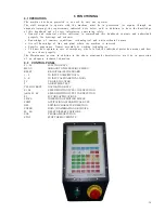
Page 17: ...turned on it indicates an error of CPU control board In case it should turn on try to press on RESET and if the situation does not improve contact AMP or your local distributor for assistance 5 3 KEYB...

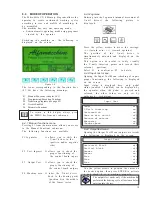
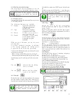
Page 18: ...status enabled disabled can be displayed by the operator when the pedal is pressed and released the other values are only set by authorised technicians 5 4 4 Output test menu Opening the Output Test M...

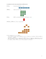
Page 19: ...the program F3 Permits the access tothe first free programming step 5 4 11 Creation of new programs To create a new frame program perform the following steps From the main menu press F2 then press F4...

Page 20: ...ess the MENU key Press MENU again to return to the main menu If one of the critical data to run the cycle is missing a message appears on the screen asking the user to either enter the missing data or...

Page 21: ...ne see chapter 4 A Pressing the F2 key makes it possible to execute a step by step test cycle of the selected program F4 Activates the horizontal clamp F5 Activates the vertical clamp F6 Ativates the...

Page 22: ...ames production Rectangular frames production resettable by pressing F3 Hexagonal frames production resettable by pressing F4 Octagonal frames production resettable by pressing F5 Press the Menu key t...

Page 23: ...it these are the min max values where the assembly will stop The max value refers to the size of programmed frame Type of frame displays the option regarding the chosen type of frame to count the prod...

Page 24: ...ting from pneumatic system and the power supply c a b l e b Assembling positions It is advisable to operate as follows in order to achieve the best results in terms of junction q u a l i t y Never dri...

Page 25: ...idth of the moulding in mm Press ENTER Press F6 Enter in the value of the working speed see chapter 5 4 11 by using the directional arrows The value of working speed is already entered with reference...

Page 26: ...2 EXECUTION OF A PROGRAM PREVIOUSLY MEMORIZED Turn on the machine by the switch placed on the floor stand position it to MOTOR ON On the screen is displayed the fig 6 1 A Press the EXE key Selected th...

Page 27: ...n the machine parts because they have not been projected to sustain the weight of persons Disconnect the power supply from the electric system disconnect the air supply Once all the operations are fin...

Page 28: ...rication V nails claw heads L shaped supports V nails guide Description Replacement every 1 000 000 V nails shot Lubricate the driver blade every 200 working hours Replacement every 5 000 000 V nails...

Page 29: ...ils height Defective V nails Replace the V nails 9 2 b Pressing the foot pedal the machine does not work Possible cause Remedy Insufficient working pressure The air pressure coming out from the compre...

Page 30: ...2 f Wishing to insert several V nails one upon the other in the same point they do not stack properly or tilt during their insertion Possiblecause Remedy Wrong V nails t replace the V nails with the...

Page 31: ...tallic mass it is enough the subdivision between the steel parts and those of other metals or alloys for a proper recycling by smelting 11 DEMOLITION 12 1 DECLARATIONS You can find here attached the f...

Page 32: ...32...

Page 33: ...33...

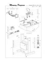
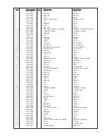
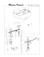
Page 34: ...Basamento Main frame 27 241300020 1 Supporto Support 28 732540003 1 Valvola Valve 29 398950030 1 Protezione Safety shield 30 248950010 1 Protezione completa Complete safety guard 31 336100020 2 Distan...

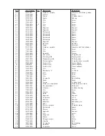
Page 35: ...r assembly 81 394950020 1 Testina H7 7mm nailhead 81 394950030 1 Testina H10 10mm nailhead 81 394950050 1 Testina H15 15mm nailhead 82 710100070 3 Vite Screw 83 384200050 1 Blocchetto L L Block 84 710...

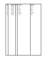
Page 36: ...7250090 1 Giunto Connector 115 334500110 1 Perno Pin 116 384600090 1 Supporto Support 117 381300070 1 Supporto Support 118 710600010 1 Vite Screw 119 336000100 1 Puleggia Pulley 120 740550009 1 Cuscin...

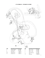
Page 37: ...0003 3 Lever Valve 732140001 4A Solenoid Valve 732440023 4B Solenoid Valve 732440023 4C Solenoid Valve 732440023 5 Exaust Valve 732390003 6 Exaust Valve 732390003 7 Exaust Valve 732390003 8 Exaust Val...

Page 38: ...38 ATTACHMENT C PLATES DISLOCATION...

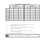
Page 39: ...soft wood such as Oak Ash Hickory Pecan Maple Cherry Ramin Other materials Horizontal grain MDF SOFT WOOD HARD WOOD A B C D E F Height mm H 3 mm H 5 mm H 7 mm H 10 mm H 12 mm H 15 mm Very soft wood HP...

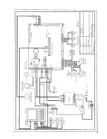
Page 40: ...40 ATTACHMENT E ELECTRIC SCHEME F1 F2 F3 Fuse F1 10 A 250 V delayed type 5x20 Fuse F2 6 3 A 250 V delayed type 5x20 Fuse F3 3 15 A 250 V delayed type 5x20...

Page 41: ...41...
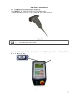
Page 42: ...e to be joined using a barcode Using a barcode scanner see pecture D 1 the program name is conveyed to the machine Picture D 1 Use a laser scanner code number 805500001 The scanner must be connected t...

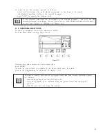
Page 43: ...h ENTER read the bar code which corresponds to the frame which must be joined execute the programming as indicated at chapter 5 4 11 In order to modify the name of a program which has been already ins...

Page 44: ...1 b Ablock of programs F2 c Alloftheprogramsfiledinthememory F3 Before transferring any programs the programs stored in the slave machine must be deleted A 1 1Transfer of a single program To transfer...

Page 45: ...en press enter Type in the 1st code line number on the Slave machine where you want to place the selected programs Press Enter to confirm the transmission A 1 3TransferingalltheprogramsstoredintheMast...

Reviews: