Installation & Commissioning of Control & Monitoring Add On’s
Page: 17
Local Control Station Terminal Blocks TB1 & TB2
TB2 Terminal
Assignment
TB1 Terminal
Assignment
1
RS485 + In
1
+27V In
2
RS485 - In
2
0V In
3 RS485
Common
3 +27V
Out
4
RS485 + Out
4
0V Out
5 RS485
-
Out
6 RS485
Common
7 In
8 Interlock-
Quiescent Current:
18.5mA
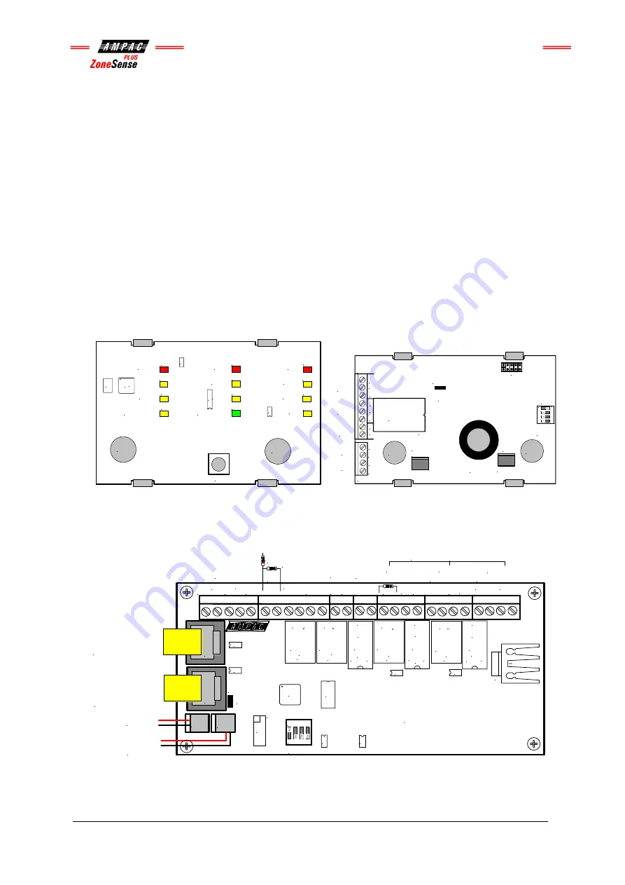
Local Control Station Layout
The Comms line is RS485 between the Local Control Station and the Termination Board.
The Interlock is a monitored input with 10K
Ω
EOL used to determine if air conditioning dampers
and doors are closed. Typically the agent is not discharged until all dampers / doors are closed.
D10
D9
D14
D13
D12
D11
D6
D5
D4
D3
D8
D7
U4
U1
U2
U3
X1
Manual Release
Activated
Initial Agent
Manual Hold
Auto / Manual
Auto Release
Activated
Reserve Agent
Trigger Zone
Disabled
Manual Only
Agent
Released
Blocked Mode
Common Fault
Disabled
Hold
Cutout
Cutout
RS 485
OUT
TB2
TB1
SW2
K1
HY1
CN5
BUZZER
BZ1
INTER
LOCK
COM
Termination
Link
Address
Switch
EC3AW
3V3 POWER
SUPPLY
+
COM
+27V
Out
0V
+27V
In
0V
+
_
+
_
RS 485
IN
+
_
+
+
1
2
3
4
ON
CN8
CN2
Key Switch
Manual Release
Cutout
Cutout
Figure 24: Top PCB Layout
Figure 25: Bottom PCB Layout
5.5
Agent Release Termination Board BRD25ATB
Figure 26: Agent Termination Board PCB Layout
LK1
Q2
SW1
U5
U9
U7
U1
RL6
RL4
RL1
RL2
RL5
RL3
CN5
U3
U4
U2
U10
RL7
+ LOCK-
+ L.PSW-
RELEASE
C
NC
NO
///
+L
COMM
NC
NO
-L
C
NC
NO
///
-
+
SIG+
SIG-
LCP CABLE
+ PSW -
Monitored
INPUTS
N/0
STAGE2
GAS
FIRED
+
-
N/0 COM
N/0 COM +
SYST.
INOP.
SCRN
+24VDC
+ -
C
NC NO
///
C
NC
NO
///
-L
NO
NC
COMM
+L
-L
NO
NC
COMM
+L
0VDC
+ -
STAGE1
-
COM
TB7
TB6
TB5
TB4
TB3
TB2
TB1
C
N
2
C
N
1
Address Setting
CN3 CN4
27V In
27V to
Next Board
RS485 Control
In From CN2 of
Previous Board
RS485 Control
Out to Next
Board or Link 1
EOL is Applied
MAIN
RESV
+ - Outputs are Monitored
Contact
Rating
1A & 24V
Contact
Rating
1A & 24V
Contact
Rating
1A & 24V
Contact
Rating
1A & 24V
1 2 3 4
O N
EOL
Termination
Quiescent Current:12mA
4K7
22K
EOL
10K
EOL
10K
EOL
10K
EOL


