background image

Date: 02 Feb 2011 

Ampair ® 300 (Mk1, “Pacific”) Wind Turbine Manual


CD 2300 

Issue: 1.2 

Page 29 of 34 


- 29 - 

© Ampair, April 2007 

Faulty rectifiers:

 The rectifiers should last the life of the machine. The most likely cause for their demise 

is  accidental  reverse  polarity  connection  of  Ampair  to  battery.  If  this  is  suspected  the  rectifier  diode 
bridges must be checked. 
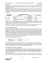
Diode Test:

 This test will show if the rectifier diodes are either open or short circuit. If your multimeter has 

a  diode  check  feature,  select  this  (if  not  select  the  highest  resistance  range)  and,  after  removing  the 
connecting wires apply the red meter lead to the red rectifier lead (disconnected from battery plus), black 
meter lead to thick black lead (disconnected from battery  minus), and note the reading. Now reverse the 
connections. 


METER LEAD 

POSITION 

MULTIMETER SETTING 

CONCLUSION 

DIODE TEST 

OHMS x 100 

Red to Red. 

No reading 

or 

many Megohms 

OK 

Reading 

or 

low resistance 

Not OK 

Black to Red 

0.5 to 1 volt (two diode drops) 

or 

markedly less* 

OK 

No reading 

or 

high resistance 

Not OK 

*This test is not as conclusive as the diode test method however, provided the first reading is a very high 
resistance  and  the  second  reading  far  lower,  then  the  test  is  valid.  Actual  values  will  depend  on  the 
voltage supplied by the particular meter for its resistance ranges. 

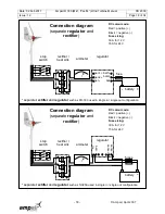
The  rectifiers  are  located  on  a  separate  heat-sink  which  should  have  been  installed  near  the  regulator. 
Unsolder the commoning links between the three rectifier outputs to check outputs separately. 
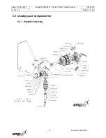
6.1.1.4


Alternator section 

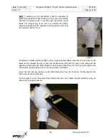
Referring to the exploded diagram of the wind turbine, undo the six M5 x 50 mm screws on the front of the 
Ampair and pull the front fore-body flange away from the main body. Do this very carefully as it must be 
withdrawn  true  or  it  will  jam  on  the  stator.  The  shaft  and  bearings  are  located  using  Loctite  anaerobic 
adhesives so some force may be necessary to part them. A puller may have to be improvised to do this. 
This job should, therefore, be done on a suitable work bench. The rear bearing needs a bearing puller to 
remove it, if no puller is available, a dummy shaft may be fixed in the bearing centre using epoxy adhesive 
and, when cured, the bearing worked loose. The front bearing may be drifted out following removal of the 
circlip.  Prior  to  re-assembly,  the  bearing  housings,  the  bearings  inner  and  outer  surfaces  and  the  shaft 
surfaces should all be thoroughly cleaned and de-greased.  

When re-assembling use adhesives as follows: 


Bearings to body 

 Loctite 641 

Shaft to bearings 

 Loctite 641 


When replacing the fore-body, make sure that the new "O" ring is in place and well smeared with silicone 
grease. Assemble the  body  checking  that  the  wiring  to the  stator  cannot  touch the  rotor.  Tighten the  six 
M5 x 50 mm bolts up slowly and evenly taking care to keep the stator parallel in the housing and tighten 
until the body sealing O ring has been evenly compressed all the way around. 

6.1.1.5


Stator and rotor replacement 

This is normally a factory operation. Rotor damage is unlikely, but sometimes occurs due to corrosion or 
other  mechanical  problems.  Considerable  force  is  necessary  to  break  the  adhesive  bond  between  the 
rotor and rotor shaft and a bearing press with guide tools to protect the shaft is needed. The magnets are 
both  very  powerful  and  brittle,  and  so  difficult  to  work  with  in  the  field.  Rotor/shaft  assemblies  can  be 
returned for replacement. 

Stator failure only normally occurs due to salt water immersion. Any accident causing this necessitates the 
immediate  cleaning  of  all  parts  with  fresh  water  and  then  drying  thoroughly.  Leaving  to  dry  naturally 

Summary of Contents for 300

Page 1: ...Date 02 Feb 2011 Ampair 300 Mk1 Pacific Wind Turbine Manual CD 2300 Issue 1 2 Page 1 of 34 1 Ampair April 2007 Ampair 300 Wind Turbine Operation Maintenance Manual ...

Page 2: ...RMANCE 25 5 1 Starting and stopping 25 5 2 Performance 26 6 INSPECTION MAINTENANCE 27 6 1 Major disassembly 27 6 2 Drawings and component list 31 6 3 Recommended spares 33 7 WARRANTY 33 8 SERVICING REPAIRS DISPOSAL 33 Disclaimer The information in this manual is believed to be correct and reliable However Ampair assumes no responsibility for inaccuracies and omissions The user of this information ...

Page 3: ... of Boost Energy Systems Ltd manufacturers of distributed energy systems for fifty years Ampair and PowerFurl are trademarks of Ampair and Boost Energy Systems Ltd The label with the model type and nominal voltage is on the electrical box cover where the name Ampair is shortened to AMPAIR The serial number of the wind turbine is stamped on the lower left side of the main body casting on the outsid...

Page 4: ...are a variety of sources of potential hazards which can result in death or serious injury These dangers exist during installation operation or inspection and maintenance 2 2 1 Mechanical dangers The main dangers are the spinning rotor and the tail The rotor blades are very sharp and can cause very serious injuries even at low speeds WARNING Never touch the rotating rotor the blades or hub Never tr...

Page 5: ...ly high If you do so there is a serious risk that you will set the battery and cabling on fire as well as releasing flammable and potentially explosive gases hydrogen from the battery and you will probably destroy the battery WARNING Never short circuit the battery Install fuses immediately adjacent to the wind turbine side of the battery but not within the battery compartment as the spark from a ...

Page 6: ...work team thoroughly including the actions in the event of an accident and or injury WARNING Whenever possible work on the ground or deck not at a height Use safety harnesses safety helmets and safety slings etc Use man rated lifting equipment and access systems Work in daylight on windless days and in calm seas Keep the work area clear plan your work have your entire equipment ready and brief the...

Page 7: ...ting systems The diagram below shows the external dimensions in millimetres mm 3 2 Technical data Nominal power 300 Watts Rated wind speed for nominal power 12 6 metres per second 25 knots or 29 miles per hour Cut in wind speed 3 metres per second 6 knots or 6 9 miles per hour Thermal cut out None Survival wind speed Storm proof Rotor diameter 1 2 metre Number of blades 3 Blade material Glass rein...

Page 8: ...se The top bearing is captive in the body the lower bearing is located in the body by a stainless steel spiral retaining ring The pivot section contains an O ring around the lower bearing to body junction and a V seal where the pivot shaft passes through the lower bearing The pivot axis passes through the centre of gravity of the assembled machine This is necessary to ensure alignment into the win...

Page 9: ...s possible so as to minimise losses due to the resistance of the wiring system For this reason the rectifier of the Pacific 300 is not fitted inside the generator but is instead supplied as a separate unit for fitting adjacent to the regulator and or battery The rectifier is a three way bridge rectifier mounted on a heat sink 3 3 3 Other system components The basic wind turbine package only consis...

Page 10: ...Ampair 300 Mk1 Pacific Wind Turbine Manual CD 2300 Issue 1 2 Page 10 of 34 10 Ampair April 2007 4 2 Wind turbine packing list The Pacific 300 Wind Turbine is packaged in recyclable cardboard cartons The cartons contain ...

Page 11: ...0mm Four 6 5mm holes each end C 1 pcs Pole C 970mm 25mm OD strut pole D 2 pcs Stay wires Terminated by thimbles and D ring nuts E 1 pcs Bag 1 Containing yoke two angle feet and backstay clamp shell F 1 pcs Bag 2 Containing one anodised aluminium alloy joiner tubes G 1 pcs Kit 1 Strut yoke feet fixings 1 pcs M6 x 40mm screw 2 pcs M6 x 35 hex screw 3 pcs M6 shakeproof washers 3 pcs M6 Nyloc nuts 1 p...

Page 12: ... Ampair 300 Basic Regulator comes in two versions the 12 volt or the 24 volt version It is not possible to convert these from one to the other The carton contains A 1 pcs Regulator 12 volt or 24 volt version B 1 pcs Operation manual 4 3 7 Pacific 300 advanced regulator The Ampair 300 Advanced Regulator comes in only one version which can be configured for either 12 volt or 24 volt use by Ampair au...

Page 13: ...These conditions are shown diagrammatically below WARNING Before a wind turbine is installed in an excessively windy location the operators must satisfy themselves that the site is suitable It may be necessary to log site wind speed and direction data at various heights prior to installing the machine Any indication of turbulence means that the generator should be re sited or raised above the turb...

Page 14: ...d and in line with the guys Anchors in soft earth may require concrete blocks or dead men Gravel or clay soils require auger type anchors see inset picture and rocky ground may need drilling and expanding rock anchors Only the eye should be visible above ground Avoid waterlogged soils which have poor holding properties Install anchor below the frost level or otherwise frost heave will eject them B...

Page 15: ...ould diminish this clearance The pole base should be mounted where the structure is very rigid 4 5 4 Mechanical installation of Pacific 300 stern mount kit a Check Ensure that a complete and undamaged set of parts has been received b Pole position The pole base fixing may be moved to one side provided that when viewed from above the angle between the strut and either wire is greater than 45 degree...

Page 16: ...s so as not to crush the mast If there is any danger of running rigging becoming entangled in the wind turbine then install stays to keep the turbine guarded 4 6 Electrical installation Electrical installation should only be performed by competent personnel who have studied this manual If in doubt ask Ampair First mechanically mount the main system components except the wind turbine then run the f...

Page 17: ...se sizing 30 A for 12 V 15 A for 24 V stop switch rectifier rectifier or integrated rectifier regulator such as the S 12 300 and S 24 300 Connection diagram rectifier or integrated regulator rectifier battery rectifier fuse stop switch ammeter DC colour code Red positive Black negative Fuse sizing 30 A for 12 V 15 A for 24 V regulator Block diagram Ideally connect the ammeter between the rectifier...

Page 18: ...ulator such as NC25A used in single in single out configuration Connection diagram separate regulator and rectifier ammeter bat regulator in sense sense battery fuse DC colour code Red positive Black negative Fuse sizing 30 A for 12 V 15A for 24 V stop switch rectifier heat sink separate rectifier and regulator such as PR 300 used in single in single out configuration Connection diagram separate r...

Page 19: ...th Up to 5 m Up to 16 ft 5 to 10 m 16 to 32 ft 10 to 18 m 32 to 60 ft 18 to 28 m 60 to 90 ft 28 to 44 m 90 to 145 ft 44 to 68 m 145 to 220 ft 68 to 110 m 220 to 360 ft Minimum cross sectional area per cable 4 mm2 12 AWG 6 mm2 10 AWG 10 mm2 8 AWG 16 mm2 6 AWG 25 mm2 4 AWG 35 mm2 2 AWG 50 mm2 1 AWG Minimum AC cable size for 24 volt wind turbine Total AC section length Up to 8 m Up to 27 ft 8 to 12 m...

Page 20: ...he cable runs and mark line ends with a positive and negative symbol to minimise risk of errors At different times and in different countries the colour schemes used in wiring systems have varied If reusing old cable runs the only way to be sure is to carefully trace all the cables and loop test them yourself during initial installation 4 7 2 Fuses and circuit breakers Fuses or miniature circuit b...

Page 21: ...er is fitted It does not apply if sense wires are used WARNING Never connect an ammeter across the supply 4 7 5 Rectifiers The purpose of a rectifier is to convert the three phase alternating current AC of the turbine to direct current DC that is useful to the battery The rectifier may either be incorporated within the regulator or mounted separately The advantage of incorporating it in the regula...

Page 22: ...e carriers may be used they protect your system from excessive battery currents in the event of a serious electrical fault If they keep blowing find out why The external fuses must be near to the battery terminals since in the event of a fault the batteries would source the fault current Check and double check polarities before making connections insert the fuses in the fuse carriers last of all A...

Page 23: ...ON The blades are very sharp Safety gloves must be worn when handling blades The outline process is 1 Item checking 2 Blade mounting 3 Further steps 4 8 1 Item checking The following items will be used during the assembly process Check all are present before starting 1 pcs Generator Hub 3 pcs Rotor blade 1 pcs Blade mounting bolt kit The blade mounting bolt kit includes 6 pcs Blade mounting bolt M...

Page 24: ...p switch to stop Put blades on blade pitching shafts in order to get all yellow labels indicating the front side of the blade turned towards the top Check and double check that the front side of the blade will be upwind and the back side of the blade will be downwind see Photo 2 The front is the flatter side of the blade and the back is the more curved side of the blade Insert one bolt and one was...

Page 25: ...ry as shown in the electrical section Insert the fuse or fuses in their carriers 5 OPERATION PERFORMANCE 5 1 Starting and stopping Starting up It is assumed that the wind turbine has been assembled and installed as above If so then remove any ropes that prevent it swivelling or the blades rotating stand well clear and turn the parking stop switch to OFF or 0 Provided there is sufficient wind and t...

Page 26: ...ewtons 16 kg 35lbs at 20 metres per second 40 knots wind speed Power Speed Curves 0 50 100 150 200 250 300 350 0 5 10 15 20 Wind Speed m sec 1 Power Watts 0 400 800 1200 1600 Speed RPM Power RPM Charging Current 0 5 10 15 20 25 30 0 5 10 15 20 Wind Speed m sec 1 Current Amps 0 5 10 15 20 25 30 Current Amps Current 12 volts Current 24 volts Open Circuit Voltage 0 10 20 30 40 50 60 70 0 500 1000 150...

Page 27: ...sistance which is of the utmost importance in hostile locations such as tropical sunshine and mountain tops The material is however subject to slow degradation due to ultra violet light which increases towards the tropics and with altitude This process is slow and when it becomes apparent as a slight crazing of the blade surface particularly along leading and trailing edges The design of the blade...

Page 28: ...brushes Uncoil the retaining ring and lift the body over the pivot The exposed slip ring must be protected from the environment if the generator is removed for further servicing When reassembling put silicone grease not petroleum grease or jelly around the shaft where it passes through the lower bearing Slide the bearing and V seal down the shaft about 20mm and wipe grease around the shaft Slide t...

Page 29: ...in body Do this very carefully as it must be withdrawn true or it will jam on the stator The shaft and bearings are located using Loctite anaerobic adhesives so some force may be necessary to part them A puller may have to be improvised to do this This job should therefore be done on a suitable work bench The rear bearing needs a bearing puller to remove it if no puller is available a dummy shaft ...

Page 30: ...11 Ampair 300 Mk1 Pacific Wind Turbine Manual CD 2300 Issue 1 2 Page 30 of 34 30 Ampair April 2007 causes the loss of stator winding insulation due to salt corrosion resulting in electrical leakage and shorted turns ...

Page 31: ...Date 02 Feb 2011 Ampair 300 Mk1 Pacific Wind Turbine Manual CD 2300 Issue 1 2 Page 31 of 34 31 Ampair April 2007 6 2 Drawings and component list 6 2 1 Exploded drawing ...

Page 32: ...ETL00002 Pivot lower plain bearing ORG59IX533 Lower plain bearing O ring SPRG00002 Spiral retaining ring SEAL VA 040 AM SP1030 Pivot shaft V seal METL00021 Pivot shaft CBLSR PG11 Cable gland ASMB00002 Brush holder assembly BRSH00001 AM SP3035 Brush set 3 off SCRM4x8 06SS M4x8 machine screws CSTM00005 Electrical box lid NMETL00006 Insulating washer SCRM4x12 12SS M4x12 self tapping screws METL00025 ...

Page 33: ...two years from the date of purchase Any faulty part will be replaced free of charge and any faulty workmanship will be rectified free of charge upon prepaid return of a unit to Ampair or any authorised agents The unit will then be returned to the customer and freight charged to the customer This guarantee does not cover mishandling accidental damage or faulty installation Nor can Ampair or its aut...

Page 34: ...ific Wind Turbine Manual CD 2300 Issue 1 2 Page 34 of 34 34 Ampair April 2007 300 complies with the WEE and RoHS directives The packaging materials are only cardboard Expanded foams have deliberately not been used as a packaging material ...

Reviews:

Related manuals for 300