background image

IntesisBox

®

 Modbus Server – Mitsubishi Heavy Industries AC  

User’s Manual r1.0 eng


© Intesis Software S.L. - All rights reserved 

This information is subject to change without notice


IntesisBox

®


is a registered trademark of Intesis Software SL


URL 
Email 
tel 

  http://www.intesis.com                                          

info@intesis.com 
+34 938047134 

13 / 26 


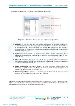
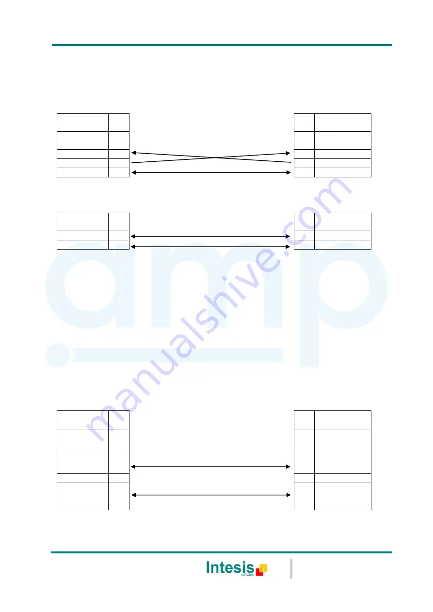
EIA485 connection: Use the C1 connector (see 

Figure 3.1

if the Modbus interface is 

a 2-wire EIA485 connector. Connect the + and 

 to the respective port in the master 

device and in the IntesisBox

®

 device (polarity matters). 


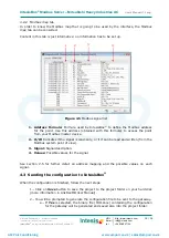
EIA232 connection: Use the C2 connector (see 

Figure 3.1

if the Modbus interface is 

point-to-point to one single master. 


IntesisBox 

(DB9 M) 

C2 

Modbus RTU Connection 


Master RTU 

(DB9 M) 

Cable 

(DB9 F) 


EIA232 

(Crossed) 


Cable 

(DB9 F) 

RX 


RX 

TX 


TX 

GND 


GND 

Table 3.3 

EIA232 cable pin assign 


Cable 

(2-wire) 


EIA485 


TX/RX+ 


TX/RX+ 

TX/RX- 


TX/RX- 


Table 3.4 

EIA485 cable pin assign 

 
To check connectivity and correct functioning, use LinkBoxMB software (see LinkBoxMB User 

Manual). 
 

3.2.2


Connect to Modbus TCP 

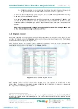
Connect  the  communication  cable  coming  from  the  hub,  switch  or  device  of  the  Modbus 
Ethernet network to the ETH connector from the IntesisBox

® 

device (see 

Figure 3.1

). The 

cable to be used may vary depending on where the IntesisBox

®

 is being connected: 


Connecting  directly  to  a  Modbus  TCP  master  device:  Crossover  Ethernet  UTP/FTP 
CAT5 cable. 


Connecting to a hub or switch of the LAN of the building: Straight Ethernet UTP/FTP 
CAT5 cable. 


IntesisBox 

(RJ45 F) 

ETH 

Modbus TCP Connection 


Master TCP 

(RJ45 F) 

Cable 

(RJ45 M) 


Ethernet 


Cable 

(RJ45 M) 


Cable UTP/FTP Cat5 Crossover 


1 device 

Modbus 

master 


Cable UTP/FTP Cat5 Straight 

Hub 

N devices 

Modbus 

master 


Table 3.5 

TCP cable connection 


AMP Air Conditioning

www.ampair.co.uk | sales@ampair.co.uk

Summary of Contents for IntesisBox

Page 1: ...sisBox Modbus Server Mitsubishi Heavy Industries Air Conditioning User s Manual Issue Date 14 05 2012 r1 0 eng Order Code MH AC MBS 48 MH AC MBS 128 AMP Air Conditioning www ampair co uk sales ampair co uk ...

Page 2: ...nder a license agreement or nondisclosure agreement The software may be used only in accordance with the terms of those agreements No part of this publication may be reproduced stored in a retrieval system or transmitted in any form or any means electronic or mechanical including photocopying and recording for any purpose other than the purchaser s personal use without the written permission of In...

Page 3: ...tware SL URL Email tel http www intesis com info intesis com 34 938047134 3 26 Gateway for integration of Mitsubishi Heavy Industries air conditioning systems into Modbus RTU and TCP systems Two models are available for this gateway with the following Order Codes MH AC MBS 48 Model supporting up to 48 indoor units MH AC MBS 128 Model supporting up to 128 indoor units AMP Air Conditioning www ampai...

Page 4: ... to ALL indoor units 10 IntesisBox Device Connections 11 3 Connect to Mitsubishi Heavy Industries Interface 12 3 1 Connect to Modbus Interface 12 3 2 3 2 1 Connect to Modbus RTU 12 3 2 2 Connect to Modbus TCP 13 3 2 3 Connect to PC LinkBoxMB 14 Power Device 14 3 3 LinkBoxMB Configuration monitoring tool for IntesisBox Modbus Server series 15 4 Introduction 15 4 1 Connections configuration 15 4 2 4...

Page 5: ...erface allowing the Modbus master read and write in the Modbus registers Moreover IntesisBox includes all hardware required to manage control Mitsubishi Heavy Industries indoor units without extra components needed Integration signals 1 2 Following is the list of parameters that can be monitored controlled on the indoor units using IntesisBox For each indoor unit in the system o Communication Stat...

Page 6: ... indoor unit if no response of a certain device is detected the corresponding virtual signal inside the gateway will be activated indicating communication error between the gateway and that precise device see 0 When a write order is done from Modbus in a gateway s write enabled Modbus address the corresponding order is sent to the associated Mitsubishi Heavy Industries signal Superlink Each Mitsub...

Page 7: ...units For Superlink I Previous Superlink or Superlink II New Superlink Indoor Unit actual address range is 00 to 47 MH AC MBS 128 Model supporting up to 128 indoor units For Superlink II New Superlink Indoor Unit actual address range is 000 to 127 Check available combination of Mitsubishi Heavy Industries Central Control and BMS interface units in the next tables In the case of SL2NA or SL3NA it i...

Page 8: ...on register contents are always expressed in MSB LSB Bid Endian Modbus error codes are fully supported they will be sent whenever a non valid Modbus action or address is required see section 9 Modbus RTU 2 3 Baud rate can be selected from 1200 2400 4800 9600 19200 and 38400 Information structure Data Bits 8 Parity Bit Selectable from non even odd or second stop bit 2stop Stop Bit 1 Modbus slave nu...

Page 9: ... Off 1 On 3 R W Operation Mode 0 Cool 1 Heat 2 Fan 3 Auto 4 Dry 4 R W SetPoint Temperature Celsius value 16ºC to 30ºC 5 R W Fan Speed 0 Low 1 Medium 2 High 3 Powerful 6 R W Remote Controller Lock Unlock 0 Remote Controller Locked 1 Remote Controller Unlocked 7 R W Louver Control2 0 Swing 1 Pos1 2 Pos2 3 Pos3 4 Pos4 8 R Room Temperature Celsius value 0ºC to 30ºC 9 R Filter Sign status 0 Off 1 On 10...

Page 10: ...ax number of supported indoor units depends on IntesisBox model 2541 R Communication Status 2542 R W Indoor Unit On Off 2543 R W Operation Mode 2544 R W SetPoint Temperature 2545 R W Fan Speed 2546 R W Remote Controller Lock Unlock 2547 R W Louver Control 2548 R Room Temperature 2549 R Filter Sign status 2550 R Indoor Unit Error Code 2551 R Compressor Status 2552 W Filter Sign Reset 2553 W Remote ...

Page 11: ...ce physical interface connector s description 1 Modbus RTU master EIA485 C1 8 Reset button Non supported 2 Modbus RTU master EIA232 C2 9 Superlink selector SLK New Superlink II Old Superlink I 3 Console serial port EIA232 10 A B connector for Superlink no polarity 4 Operation LED 11 Modbus TCP master Ethernet ETH 5 Error LED 12 Power supply On Off button 6 Host LED 13 Power supply fuse 250V 1 5A 7...

Page 12: ...ctions parallel wiring with the power line should be avoided Select the appropriate Superlink mode in the SLK selector If you are using latest Air Conditioner of the Mitsubishi Heavy Industries network New Superlink select NEW if not select OLD LEDs placed in the top left corner will show connection status as follows LED Status IntesisBox behavior OP Blinking Power supply OK ERR Off No error HOST ...

Page 13: ... GND Table 3 3 EIA232 cable pin assign Cable 2 wire EIA485 TX RX TX RX TX RX TX RX Table 3 4 EIA485 cable pin assign To check connectivity and correct functioning use LinkBoxMB software see LinkBoxMB User Manual 3 2 2 Connect to Modbus TCP Connect the communication cable coming from the hub switch or device of the Modbus Ethernet network to the ETH connector from the IntesisBox device see Figure 3...

Page 14: ... 2 3 Connect to PC LinkBoxMB Connect the IntesisBox device to the PC serial port using the serial cable provided One end should be connected to the Console EIA232 port of the IntesisBox device see Figure 3 1 and the other end to the PC serial port IntesisBox DB9 F EIA232 Serial Console PC Connection LinkBoxMB PC DB9 M Cable DB9 M EIA232 Straight Cable DB9 F TX 2 2 RX RX 3 3 TX GND 5 5 GND Table 3 ...

Page 15: ...sisBox device In this section only the specific case of Mitsubishi Heavy Industries indoor unit s integration to Modbus networks will be covered Connections configuration 4 2 To configure the IntesisBox s connection parameters and to see the points list press on the Config button in the menu bar see Figure 4 1 The Mitsubishi Heavy Industries Configuration window will open see Figure 4 2 For integr...

Page 16: ...er the IP netmask for IntesisBox 4 Gateway Enter the default gateway address for IntesisBox leave it blank if no router is needed 5 Port Enter the TCP port to use default for Modbus TCP is 502 6 Timeout Keep Alive Enter the time expressed in seconds that IntesisBox will wait upon no TCP activity to send a Keep Alive packet Enter 0 if you don t want IntesisBox to send any Keep Alive packet default ...

Page 17: ...ration tasks 2 Gateway version Selection of the IntesisBox Modbus Server Mitsubishi Heavy Industries gateway you are setting up 128AC for MH AC MBS 128 48AC for MH AC MBS 48 3 Timeout response Maximum amount of time permitted before activating the Communication Error signal It is expressed in milliseconds ms and ranges can vary from 2000 ms to 10000 ms 4 Delay interframe Maximum amount of time per...

Page 18: ...his formula to access the point from your Modbus master device 2 R W Indicates if the signal is read only or if it can be read and written from the Modbus system point of view 3 Signal Signal description 4 Values Possible values for the signal See section 2 5 for further detail on address mapping and the possible values on each signal Sending the configuration to IntesisBox 4 3 When the configurat...

Page 19: ... configuration change do not forget to send the configuration file to the IntesisBox using button Send File Signals viewer 4 4 Once the gateway is running with the correct configuration to supervise the status of the configured signals press the Signals button on the menu bar see Figure 4 1 The Signals Viewer window will open see Figure 4 6 This window shows all signals active within the gateway w...

Page 20: ...B saves the integration configuration in the following files inside the project folder PROJECT INI INI file containing general information related to the project MHI INI INI file containing information related with the values configured through the Connection tab in IntesisBox configuration MHI LBOX Binary file created from the information in the files described above This is the file downloaded t...

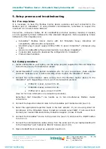
Page 21: ... on your laptop use the setup program supplied for this and follow the instructions given by the Installation wizard 2 Install IntesisBox in the desired installation site For your convenience check external enclosure measures see 7 before deciding where to place the IntesisBox device 3 Connect the communication cable coming from the Modbus master device to the IntesisBox port Depending on the type...

Page 22: ...inking once perdiodicaly Superlink communication failure Check Superlink cables and terminals connectors length of cables etc HOST Off Configuration error Download the binary file again see 4 3 PAC Off Communication error in the Superlink network Check the Mitsubishi Heavy Industries Superlink network and its connections Table 5 1 IntesisBox LED status information 5 3 2 Software checking Once phys...

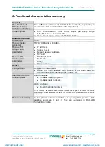
Page 23: ... Modbus modes supported TCP RTU EIA232 or EIA485 Modbus TCP configuration parameters IP address Subnet mask Default gateway address TCP port Modbus RTU configuration parameters EIA232 EIA485 Baud rate Parity Slave number Points Configuration AC system related fields Indoor unit main address Main Address of the indoor each AC indoor unit Modbus memory block relates to Supported Modbus function code...

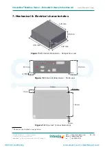
Page 24: ...are SL URL Email tel http www intesis com info intesis com 34 938047134 24 26 Mechanical Electrical characteristics 7 1 Device can be installed in any position Ø 5 mm 195 mm 138 mm 10 mm 15 mm Figure 7 1 External dimensions Perspective view Figure 7 3 Top view1 screw holes size 215 mm 167 mm 65 mm 179 mm 61 mm 4 mm 65 mm Figure 7 2 External dimensions Front view 61 mm AMP Air Conditioning www ampa...

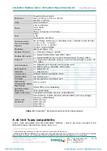
Page 25: ...ort link and activity LNK ACT 4 x MHI Interface OP ERR HOST PAC Push buttons 1 x Reset Device Selectors 1 x SLK selector Console port EIA232 DB9 female DCE SELV Configuration Via console port 2 Firmware Allows upgrades via console port Operational temperature range 0 C to 40 C Operational humidity range 5 to 95 non condensing Protection IP20 IEC60529 RoHS conformity Compliant with RoHS directive 2...

Page 26: ...o 32 E32 Open L3 Phase on power supply at primary side 33 E33 Inverter primary current error 35 E35 Cooling overload operation 36 E36 Discharge pipe temperature error 37 E37 Outdoor heat exchanger temperature thermistor anomaly 38 E38 Outdoor Ambient air temperature thermistor anomaly 39 E39 Discharge pipe temperature thermistor anomaly 40 E40 High pressure error 41 E41 Power transistor overheat 4...

Reviews: