BAT7001 Version 2 USER MANUAL ISSUE 1
-1-
1.
Application
A source of auxiliary power is generally
required in circuit breaker applications in
order to:
1.
Provide power to close and trip coils.
2.
To allow protective relays to operate
reliably.
In
certain
applications
it
may
be
uneconomic (remote installations) or
contrary
to
safety
regulations
(eg.
underground coal mines) to use a battery to
provide auxiliary power.
It is not recommended to derive auxiliary
power directly from the local AC supply.
Under fault conditions this voltage may
instantaneously fall to a level below which
either the circuit breaker shunt trip coil or
the protective relay may not operate
correctly.
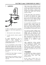
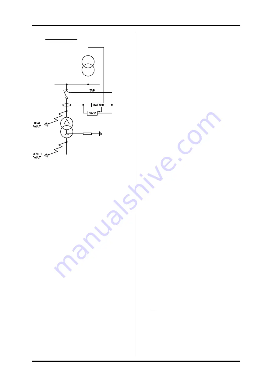
The BAT7001 Power Supply is designed
to overcome these problems.
Under normal load conditions it uses the
upstream voltage source to charge storage
capacitors.
Under remote fault conditions the local
voltage will be depressed, but the current
can be expected to be greater than the rated
current. This current is used by the
BAT7001 Power Supply to supplement the
available input voltage and so keep the
capacitors charged.
For three phase faults in close proximity to
the substation the substation bus voltage
can fall to zero, however the current
present at the BAT7001 Power Supply’s
inputs will be several multiples of rated
current and is used to ensure that the
capacitors remain fully charged.
It is not generally recommended to use the
BAT7001 Power Supply without the
presence of upstream voltage transformers.
This is due to the fact that the BAT7001
Power Supply would not be charged up at
the instant that the circuit breaker is closed.
If a "switch on to fault" condition occurs,
without the BAT7001 Power Supply being
supplied from an upstream VT, the
available fault current would charge up the
BAT7001 Power Supply, but only after a
finite time period. This additional time
delay in tripping the circuit may not be
acceptable and is eliminated by the
connection
to
an
upstream
voltage
transformer.
Where applications without upstream
voltage transformers are implemented the
use of transistorised protective relays
rather than microprocessor relays is
preferred. This is because microprocessor
relays generally undergo a start up routine
upon power up and this may last several
seconds.
2. Description
The BAT7001 Power Supply is designed
to supply a DC voltage for the tripping of
circuit breakers and/or power other
protection devices.
The DC voltage is derived from a 110
VAC supply and three 1 or 5 amp Current


