Ampcontrol Pty Ltd
– ABN 28 000 915 542
EFL PROTECTION RELAY USER MANUAL
MAG-178 Version 5
– MARCH/2020
Uncontrolled Copy - Refer to Ampcontrol Website for Latest Version
Page 13 of 23
A
P
P
R
OV
E
D
FOR
E
X
T
E
R
N
A
L
D
IS
TR
IB
U
T
ION
–
P
R
OP
E
R
T
Y
OF
A
M
P
C
ON
TR
OL
P
T
Y
LTD
–
N
O
T
T
O
B
E
R
E
P
R
OD
U
C
E
D
I
N
P
A
R
T
4.4 Electrical Installation Information
Upstream
Circuit Breaker
To Indication Circuit
(Energised When Healthy)
To Indication Circuit
(Energised When Healthy)
24Vdc or 24Vac
Supply
21 (or 22, 23, 24)
To CB UV
Coil Supply
EFL
Main
Contactor
A
B
C
A
B
C
Trailing/Reeling Cable
UV
External
Barrier
(If Used)
MC
Main Contactor
Auxiliary Contact
14
13
10
9
CBR-NO
CBR-COM
15
CBR-NC
MCR-NO
MCR-COM
MCR-NC
17
18
MCI-NO
MCI-COM
29
30
31
EARTH
VcmA
VcmB
1
POWER1
2
POWER2
5
6
7
8
25
26
NC
COM
EFLO TRIP
INDICATION
FC TRIP
INDICATION
NC
COM
RESET-NO
RESET-COM
EFLO & UV Trip Reset
N/O Pushbutton
Load
NOTE: TERMINALS 3, 4, 12 & 16
ARE NOT CONNECTED
RUN-NO
RUN-COM
EARTH
A
B
C
EFL
Flying Leads
Internal Barrier Connections
VcmC
32
VcmA
VcmB
VcmC
EARTH
Ua
Ub
Uc
5
6
7
8
START
MC-STOP
EFL-MCR
INT
Typical Control Schematic:
INT
INT
MC
CB-STOP
EFL-CBR
UV
RUN INPUT
FC TRIP RESET
PUSHBUTTON
11
Interposing Relay
19
INT
20
Interposing Coil Supply
Enclosure
MC Coil Supply
C
o
n
ta
ct
s E
n
er
gis
ed
W
h
en
H
ea
lth
y
Test Delay Input
27
28
TEST
DELAY
NO
COM
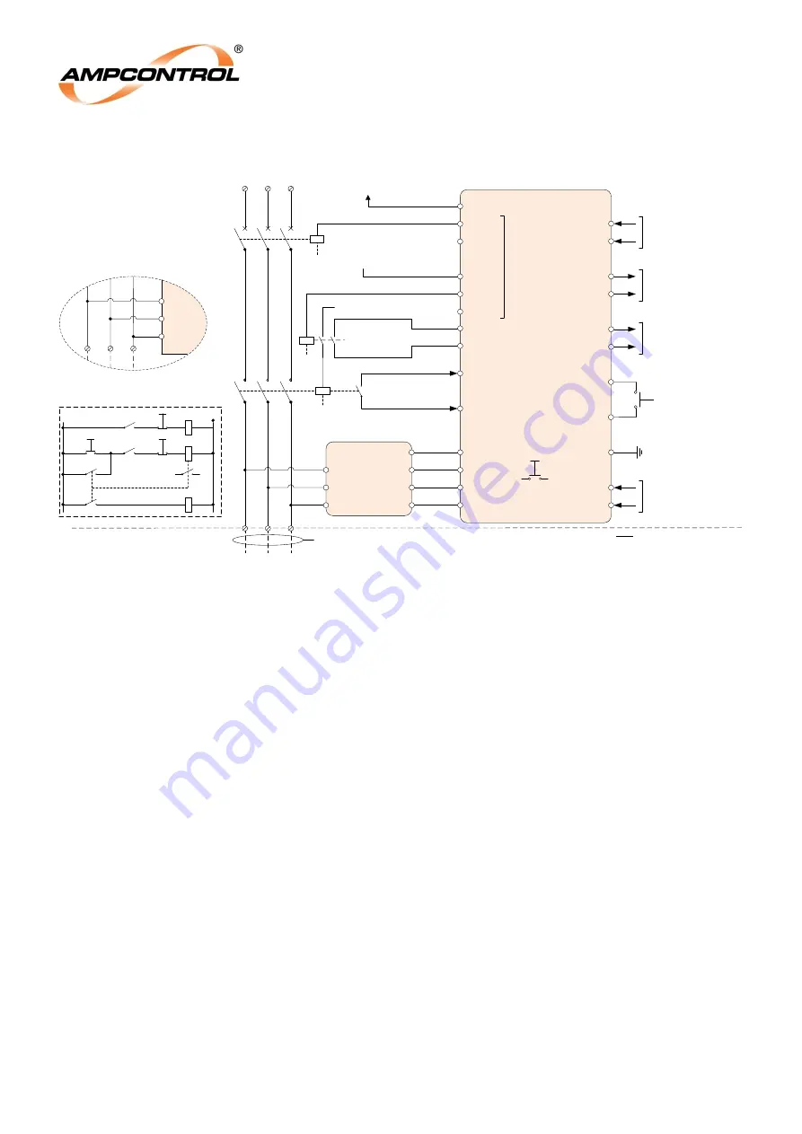
Figure 4.6: Typical Electrical Application
4.4.1 Power Supply (Terminals 1 & 2)
The EFL relay is supplied by either 24Vdc ± 20% or 24Vac ± 20%. The power consumption of the relay
is less than 5W.
4.4.2 Earth Fault Lockout (EFLO) Trip Indication (Terminals 5 & 6)
The EFLO Trip Indication Contact is a normally closed (NC) contact that is used to provide external
indication that an EFLO trip has occurred. The contact is energised when the system is healthy and will
de-energise (close) when an EFLO trip is active.
4.4.3 Frozen Contactor (FC) Trip Indication (Terminals 7 & 8)
The FC Trip Indication Contact is a normally closed (NC) contact that is used to provide external
indication that an FC trip has occurred. The contact is energised when the system is healthy and will
de-energise (close) when an FC trip is active.
4.4.4 Main Contactor Relay (MCR) (Terminals 9, 10 & 11)
The MCR relay is the EFL’s control relay for the main contactor. The relay is a change-over, allowing
the control circuit to be implemented with either normally open or normally closed MCR.
The MCR relay is intended to be wired into the control circuit for the main contactor’s interposing circuit
relay (INT), see Figure 4.6. The MCR will energise when the system is deemed healthy, allowing power
to be applied to the interposing relay when required. When the system cannot be deemed healthy,
either when the EFL is starting, in a tripped state or immediately after the contactor has opened (prior
to EFLO test being performed), the MCR relay will be de-energised, preventing the interposing relay
from energising and hence preventing the main contactor from closing.
4.4.5 Circuit Breaker Relay (CBR) (Terminals 13, 14 & 15)
The CBR relay is the EFL
’s control relay for the upstream circuit breaker. The relay is a change-over,
allowing the control circuit to be implemented with either normally open or normally closed CBR.


